


CHAPTER 4: CONTROLS
2 KHZ INVERTER WEDLING POWER SUPPLY
4-10
990-057
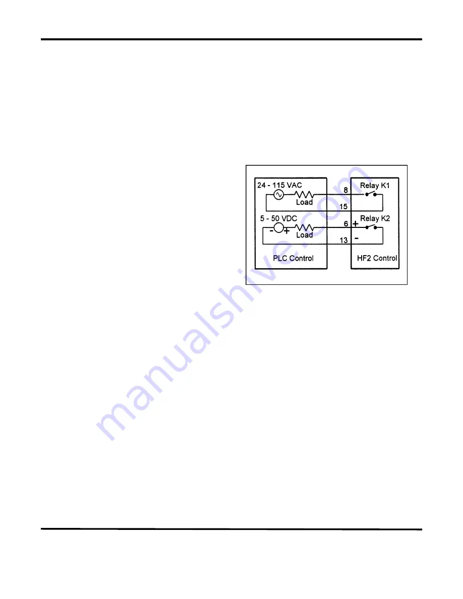
Control Signals - Output Relays (Figure 4-8)
There are two output relays which can be used to provide status or timing signals to a user Programmable
Logic Control (PLC) or Host Computer. Relay K1 can switch a 24 to 115 VAC signal. Relay K2 can
switch a 5 to 50 VDC signal. When used for status signals, these relays can be independently programmed
to close (a) when the Power Supply is initiated; (b) when any portion of the welding process is completed;
(c) when the Firing Switch opens; or (d) when the Power Supply is waiting for the welding process
sequence to start.
Relay K1 (Figure 4-10)
1
Connect a 24 to 115 VAC voltage source
and PLC load to Pins 8 and 15 on the
Control Signals Connector. Maximum
relay current is limited to 250 ma.
2
Relay K1 is also used to control the Air
Valve 2 Driver for sequentially
activating a second Air Actuated Weld
Head. Refer to
Chapter 3, AMADA
WELD TECH, Force Fired, Dual Air
Actuated Weld Head System
for
complete instructions to set up and
operate two sequential action Air
Actuated Weld Heads. When MENU,
OPTIONS 2, WELD TYPE: is set to
Figure 4-10. Relay K and K2 Connections
DUAL AIR, the options for RELAY 1 must be either AIR HEAD 2 or NOT USED. Air Valve
2 Driver will be actuated in any Schedule in which RELAY 1 is defined as AIR HEAD 2. Air
Valve 1 Driver is actuated in any Schedule in which RELAY 1 is defined as NOT USED.
Relay K2 (Figure 4-10)
Connect a 5 to 50 VDC voltage source and PLC load to Pins 6 (Positive) and 13 (Negative) on the
Control Signals Connector. Maximum relay current is limited to 250 ma.
Accessory Port (Figure 4-2)
A 25-pin, sub-miniature D-type connector, located on the rear panel, is provided to control other
devices contemplated for future expansion.


