


APPENDIX H: DEFINING THE OPTIMUM PROCESS
2 KHZ INVERTER WEDLING POWER SUPPLY
H-6
990-057
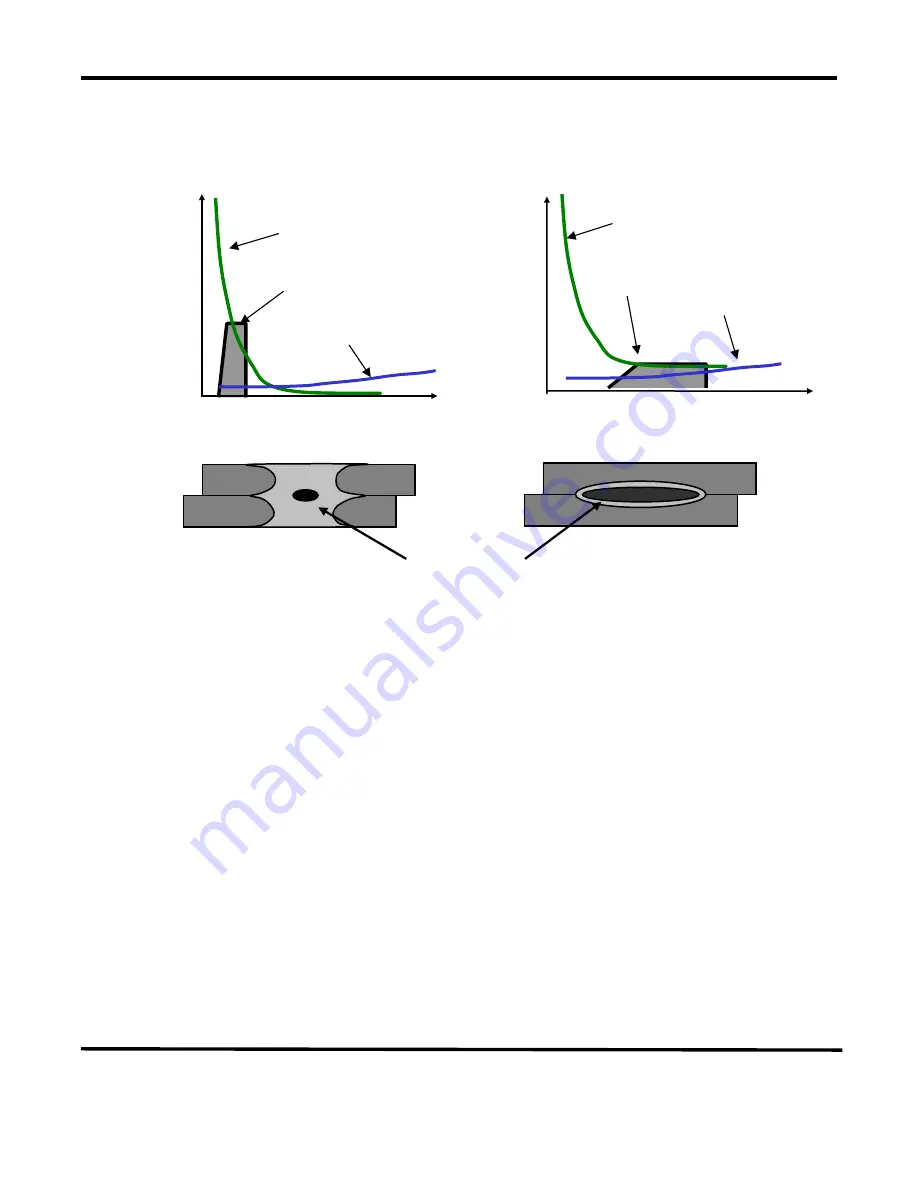
The figure below shows a weld that is fired
early on in the weld sequence when the contact
resistance is still quite high.
The figure shows a weld that is initiated when the
contact resistance is lower; in this example, we are
using bulk resistance to generate our weld heat.
In general, conductive materials benefit from a faster heating rate, as the higher contact resistances assist
heat generation in the weld. Resistive materials benefit from slower heating rates which allow the contact
resistances to reduce significantly. Bulk resistances, therefore, become the major source for heat
generation. The heat-affected zone is also much smaller in this case producing a weld with less variation.
The following figure shows the three stages of heat generation for resistive materials in a fusion weld. In
the first stage, the heat is focused in the part-to-part and electrode-to-part contact areas, since contact
resistance is high relative to bulk resistance. In the second stage, contact resistance decreases as the
electrodes seat better to the parts. Less heat is generated in the electrode-to-part contact areas, and a
greater amount of heat is generated in the parts as the bulk resistance increases. In the third stage, the
bulk resistance becomes the dominant heat-generating factor and the parts can reach their bonding
temperature at the part-to-part interface. The stages of heat generation for conductive materials will be
similar to that of resistive materials, but there will be less heat generated in the bulk resistance due to the
conductivity of the materials.
Time
Bulk Resistance
Resistance
Contact Resistance
Weld Pulse
Heat Affected Zone
(NOTE: Larger nuggets are possible with longer weld times when using bulk resistance.)
Resistance
Bulk Resistance
Time
Contact Resistance
Weld Pulse


