44
Chapter 3: Testing Performance
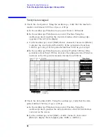
To test the single-clock, single-edge, state acquisition
c
Click the Master buttons for the remaining clocks and select Don't Care
to turn off the other clocks.
d
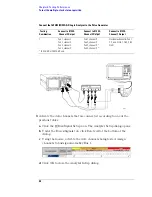
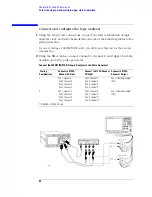
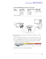
Connect the clock to be tested to the pulse generator channel 1 output.
e
Click OK to close the Analyzer Setup dialog.
5
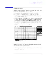
Verify the test data:
a
Click the
Run icon.
b
If you have not already done so, do “Set up the Markers:” on page 34.
c
If the "can't find 4096 occurence(s)" message does not appear, the test
passes.
The test passes when the logic analyzer finds all occurances of the patterns
programmed into the Markers. If the test passes, record a "Pass" in the
performance test record under single-clock single-edge next to the clock and
edge being tested.
6
Test the next clock:
a
Click on the
Sampling Setup icon.
b
Disconnect the clock just tested from the pulse generator.
c
Repeat steps 4, 5, and 6 for the next clock configuration listed in step 4
until all listed clock combinations have been tested.
7
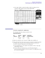
Enable the pulse generator channel 1 COMP (with the LED on).
8
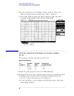
Using the Delay mode of the pulse generator channel 1, position the pulses
according to the setup/hold combination selected, +0.0 ps or –100 ps as
measured on the oscilloscope:
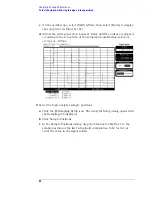
a
On the Oscilloscope, select [Define meas] Define
∆
Time - Stop edge:
falling.
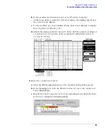
b
On the oscilloscope, select [Shift]
∆
Time. Select Start src: channel 1,
Summary of Contents for 1680 series
Page 13: ...13 Chapter 1 General Information Dimensions 1680A AD Series 1690A AD Series...
Page 74: ...74 Chapter 3 Testing Performance Performance Test Record...
Page 142: ...142 Chapter 6 Replacing Assemblies 1690A AD series disassembly assembly...
Page 172: ...172 Chapter 8 Theory of Operation Self Tests Descriptions...
Page 174: ......

