


89
Using the Trigger Menu
Arming and Additional Instruments
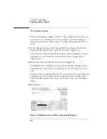
To arm the oscilloscope with the analyzer
(HP 1660ES-series only)
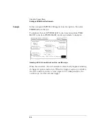
If both analyzer and the oscilloscope are turned on, you can configure
one analyzer to arm the other analyzer and the oscilloscope. An
example of this is when a state analyzer triggers on a bit pattern, then
arms a timing analyzer and the oscilloscope which capture and display
the waveform after they trigger.
1
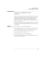
In the Analyzer Trigger menu, select Arming Control.
2
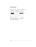
Select the Analyzer Arm Out Sent From field, and choose from
the list the Analyzer that will generate the arm.
3
Select the Analyzer Arm In field, and choose Group Run.
This allows you to time-correlate the data from the analyzers and the
scope. The Scope Trigger Mode must be Immediate for correlation.
4
Select the field of the instrument which will arm the others, and
in the pop-up set it to run from Group Run.
The Scope field is not selectable. To set how the scope is run, select the
field under Scope Arm In.
5
Select the other instrument fields and choose the mechanism
which will arm them.
The Analyzer Arm Out field determines which analyzer sends the
arming signal to Port Out and to the oscilloscope if the oscilloscope is
being armed by an analyzer.
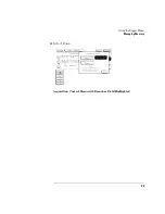
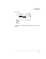
As you set each machine, the arrows connecting the fields in the
Arming Control menu change. The arrows show the order in which the
instruments are armed.
See the example on the next page.
6
Select Done until you are back at the Trigger menu.
Summary of Contents for 1670E Series
Page 6: ...6 In This Book...
Page 26: ...26 Contents...
Page 27: ...27 Section 1 Logic Analyzer...
Page 28: ...28...
Page 29: ...29 1 Logic Analyzer Overview...
Page 39: ...39 2 Connecting Peripherals...
Page 49: ...49 3 Using the Logic Analyzer...
Page 72: ...72 Using the Logic Analyzer The Inverse Assembler...
Page 73: ...73 4 Using the Trigger Menu...
Page 101: ...101 5 Using the Oscilloscope...
Page 151: ...151 6 Using the Pattern Generator...
Page 199: ...199 7 Triggering Examples...
Page 237: ...237 8 File Management...
Page 249: ...249 9 Logic Analyzer Reference...
Page 360: ...360 Logic Analyzer Reference The Compare Menu...
Page 361: ...361 10 System Performance Analysis SPA Software...
Page 397: ...397 11 Logic Analyzer Concepts...
Page 430: ...430 Logic Analyzer Concepts The Analyzer Hardware Oscilloscope board theory Oscilloscope board...
Page 439: ...439 12 Troubleshooting the Logic Analyzer...
Page 455: ...455 13 Specifications...
Page 471: ...471 14 Operator s Service...
Page 479: ...479 Operator s Service Troubleshooting Troubleshooting Flowchart 2...
Page 491: ...491 Section 2 LAN...
Page 492: ...492...
Page 493: ...493 15 Introducing the LAN Interface...
Page 497: ...497 16 Connecting and Configuring the LAN...
Page 506: ...506 Connecting and Configuring the LAN Connecting and Configuring the LAN...
Page 507: ...507 17 Accessing the Logic Analyzer File System Using the LAN...
Page 515: ...515 18 Using the LAN s X Window Interface...
Page 527: ...527 19 Retrieving and Restoring Data Using the LAN...
Page 539: ...539 20 Programming the Logic Analyzer Using the LAN...
Page 546: ...546 Programming the Logic Analyzer Using the LAN Programming the Logic Analyzer Using the LAN...
Page 547: ...547 21 LAN Concepts...
Page 555: ...555 22 Troubleshooting the LAN Connection...
Page 580: ...580 Troubleshooting the LAN Connection Getting Service Support...
Page 581: ...581 Section 3 Symbol Utility...
Page 582: ...582...
Page 583: ...583 23 Symbol Utility Introduction...
Page 588: ...588 Symbol Utility Introduction Symbol Utility Introduction...
Page 589: ...589 24 Getting Started with the Symbol Utility...
Page 597: ...597 25 Using the Symbol Utility...
Page 609: ...609 26 Symbol Utility Features and Functions...


