


408
Logic Analyzer Concepts
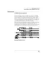
Transitional Mode Theory (1660E/ES/EP-series only)
Other transitional timing considerations
Pod pairs are independent.
In single run mode, each pod pair runs
independently. This means when one pod pair fills its trace buffer it will
not shut the others down. If you have a pod pair with enabled data lines
and no transitions on its lines, you get a message "Storing transitions
after trigger for pods nn/nn." In repetitive run mode, a full pod pair
waits 2 seconds, then halts all other pod pairs.
Increasing duration of storage.
In the 125-MHz mode, a transition
on any one of the 34 bits in a sample (if they are all turned on) will
cause storage. Reducing the number of bits that are turned on for any
one pod pair will more than likely increase data storage time.
Separating data lines which contain frequent transitions from lines with
less frequent transitions also helps. When doing this, be sure to cross
pod pair boundaries. It does not help to move fast lines from pod 1 to
pod 2; fast lines must be moved to pod 3, a different pod pair.
In the 250-MHz mode, a transition on any one of 17 bits (half-channel)
each sample (if they are all turned on) will cause storage.
Invalid data.
The analyzer only looks for transitions on data lines that
are turned on. Data lines that are turned off store data, but only when
one of the lines that is turned on transitions. If the data line is turned
on after a run, you would see data, but it is unlikely that every
transition that occurred was captured.
Summary of Contents for 1670E Series
Page 6: ...6 In This Book...
Page 26: ...26 Contents...
Page 27: ...27 Section 1 Logic Analyzer...
Page 28: ...28...
Page 29: ...29 1 Logic Analyzer Overview...
Page 39: ...39 2 Connecting Peripherals...
Page 49: ...49 3 Using the Logic Analyzer...
Page 72: ...72 Using the Logic Analyzer The Inverse Assembler...
Page 73: ...73 4 Using the Trigger Menu...
Page 101: ...101 5 Using the Oscilloscope...
Page 151: ...151 6 Using the Pattern Generator...
Page 199: ...199 7 Triggering Examples...
Page 237: ...237 8 File Management...
Page 249: ...249 9 Logic Analyzer Reference...
Page 360: ...360 Logic Analyzer Reference The Compare Menu...
Page 361: ...361 10 System Performance Analysis SPA Software...
Page 397: ...397 11 Logic Analyzer Concepts...
Page 430: ...430 Logic Analyzer Concepts The Analyzer Hardware Oscilloscope board theory Oscilloscope board...
Page 439: ...439 12 Troubleshooting the Logic Analyzer...
Page 455: ...455 13 Specifications...
Page 471: ...471 14 Operator s Service...
Page 479: ...479 Operator s Service Troubleshooting Troubleshooting Flowchart 2...
Page 491: ...491 Section 2 LAN...
Page 492: ...492...
Page 493: ...493 15 Introducing the LAN Interface...
Page 497: ...497 16 Connecting and Configuring the LAN...
Page 506: ...506 Connecting and Configuring the LAN Connecting and Configuring the LAN...
Page 507: ...507 17 Accessing the Logic Analyzer File System Using the LAN...
Page 515: ...515 18 Using the LAN s X Window Interface...
Page 527: ...527 19 Retrieving and Restoring Data Using the LAN...
Page 539: ...539 20 Programming the Logic Analyzer Using the LAN...
Page 546: ...546 Programming the Logic Analyzer Using the LAN Programming the Logic Analyzer Using the LAN...
Page 547: ...547 21 LAN Concepts...
Page 555: ...555 22 Troubleshooting the LAN Connection...
Page 580: ...580 Troubleshooting the LAN Connection Getting Service Support...
Page 581: ...581 Section 3 Symbol Utility...
Page 582: ...582...
Page 583: ...583 23 Symbol Utility Introduction...
Page 588: ...588 Symbol Utility Introduction Symbol Utility Introduction...
Page 589: ...589 24 Getting Started with the Symbol Utility...
Page 597: ...597 25 Using the Symbol Utility...
Page 609: ...609 26 Symbol Utility Features and Functions...


