


226
Triggering Examples
Cross-Arming Trigger Examples
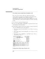
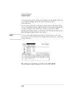
To detect a glitch
The following setup uses a state analyzer to capture state flow
occurring at the time of the glitch. This can be useful in
troubleshooting. For example, you might find that the glitch is ground
bounce caused by a number of simultaneous signal transitions.
1
Set up a timing analyzer and a state analyzer.
2
Go to the timing analyzer’s Format menu and set the Timing
Acquisition Mode to Glitch Half Channel 125 MHz.
Glitch mode only allows you to use one pod of a pod pair at a time. If
the wrong pod is active, toggle by selecting the Pod button.
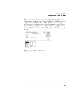
3
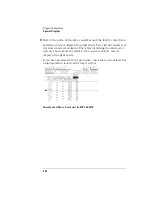
Go to the timing analyzer’s Trigger menu.
4
Select an Edge term. Then assign glitch detection "*" to the
channels of interest represented by the Edge term.
5
Go to the state analyzer’s Trigger menu.
6
Set the analyzer to be armed by the timing analyzer. Leave the
trigger set to trigger on any state.
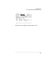
If you don’t see the activity of interest in the state trace, try changing
the trigger position using the Acquisition Control field in the Trigger
menu of the state analyzer. By changing the Acquisition mode to
manual, you can position the trigger at any state relative to analyzer
memory.
NOTE:
The timing analyzer can detect glitch activity on a waveform. A glitch is
defined as two or more transitions across the logic threshold between adjacent
timing analyzer samples.
Summary of Contents for 1670E Series
Page 6: ...6 In This Book...
Page 26: ...26 Contents...
Page 27: ...27 Section 1 Logic Analyzer...
Page 28: ...28...
Page 29: ...29 1 Logic Analyzer Overview...
Page 39: ...39 2 Connecting Peripherals...
Page 49: ...49 3 Using the Logic Analyzer...
Page 72: ...72 Using the Logic Analyzer The Inverse Assembler...
Page 73: ...73 4 Using the Trigger Menu...
Page 101: ...101 5 Using the Oscilloscope...
Page 151: ...151 6 Using the Pattern Generator...
Page 199: ...199 7 Triggering Examples...
Page 237: ...237 8 File Management...
Page 249: ...249 9 Logic Analyzer Reference...
Page 360: ...360 Logic Analyzer Reference The Compare Menu...
Page 361: ...361 10 System Performance Analysis SPA Software...
Page 397: ...397 11 Logic Analyzer Concepts...
Page 430: ...430 Logic Analyzer Concepts The Analyzer Hardware Oscilloscope board theory Oscilloscope board...
Page 439: ...439 12 Troubleshooting the Logic Analyzer...
Page 455: ...455 13 Specifications...
Page 471: ...471 14 Operator s Service...
Page 479: ...479 Operator s Service Troubleshooting Troubleshooting Flowchart 2...
Page 491: ...491 Section 2 LAN...
Page 492: ...492...
Page 493: ...493 15 Introducing the LAN Interface...
Page 497: ...497 16 Connecting and Configuring the LAN...
Page 506: ...506 Connecting and Configuring the LAN Connecting and Configuring the LAN...
Page 507: ...507 17 Accessing the Logic Analyzer File System Using the LAN...
Page 515: ...515 18 Using the LAN s X Window Interface...
Page 527: ...527 19 Retrieving and Restoring Data Using the LAN...
Page 539: ...539 20 Programming the Logic Analyzer Using the LAN...
Page 546: ...546 Programming the Logic Analyzer Using the LAN Programming the Logic Analyzer Using the LAN...
Page 547: ...547 21 LAN Concepts...
Page 555: ...555 22 Troubleshooting the LAN Connection...
Page 580: ...580 Troubleshooting the LAN Connection Getting Service Support...
Page 581: ...581 Section 3 Symbol Utility...
Page 582: ...582...
Page 583: ...583 23 Symbol Utility Introduction...
Page 588: ...588 Symbol Utility Introduction Symbol Utility Introduction...
Page 589: ...589 24 Getting Started with the Symbol Utility...
Page 597: ...597 25 Using the Symbol Utility...
Page 609: ...609 26 Symbol Utility Features and Functions...


