


142
Using the Oscilloscope
The Scope Marker Menu
Overlay and waveform math traces cannot be selected for voltage
marker placement.
The Vb On field works similarly.
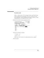
Va Volts field
The Va marker is shown on the waveform display as a horizontal
dashed line. The voltage displayed in the Va Volts field is measured
relative to the zero-volt reference for this channel.
When you select the Va Volts field, you can change the voltage value by
turning the knob or by entering a voltage value from the pop-up
keypad. The range of voltage levels for the Va Volts field is Ê2 times
maximum range for the selected channel. The maximum range value is
affected by the probe factor and v/div settings.
The Vb Volts field works similarly.
Va to Vb field
This field displays the difference between the Va and Vb markers. This
value is dependent on channel selections and represents Vb minus Va.
Center Screen Field
The Center Screen field appears on the right side of the Marker menu.
The Center Screen field centers the screen on the chosen timebase
marker.
If time markers are turned off, the only marker choice available on the
Center screen pop-up will be the trigger marker. If time markers are
turned on, the Tx and To markers will also appear in the Center Screen
pop-up menu. If the auto time markers are enabled, only the trigger
marker appears in the Center Screen pop-up menu.
Summary of Contents for 1670E Series
Page 6: ...6 In This Book...
Page 26: ...26 Contents...
Page 27: ...27 Section 1 Logic Analyzer...
Page 28: ...28...
Page 29: ...29 1 Logic Analyzer Overview...
Page 39: ...39 2 Connecting Peripherals...
Page 49: ...49 3 Using the Logic Analyzer...
Page 72: ...72 Using the Logic Analyzer The Inverse Assembler...
Page 73: ...73 4 Using the Trigger Menu...
Page 101: ...101 5 Using the Oscilloscope...
Page 151: ...151 6 Using the Pattern Generator...
Page 199: ...199 7 Triggering Examples...
Page 237: ...237 8 File Management...
Page 249: ...249 9 Logic Analyzer Reference...
Page 360: ...360 Logic Analyzer Reference The Compare Menu...
Page 361: ...361 10 System Performance Analysis SPA Software...
Page 397: ...397 11 Logic Analyzer Concepts...
Page 430: ...430 Logic Analyzer Concepts The Analyzer Hardware Oscilloscope board theory Oscilloscope board...
Page 439: ...439 12 Troubleshooting the Logic Analyzer...
Page 455: ...455 13 Specifications...
Page 471: ...471 14 Operator s Service...
Page 479: ...479 Operator s Service Troubleshooting Troubleshooting Flowchart 2...
Page 491: ...491 Section 2 LAN...
Page 492: ...492...
Page 493: ...493 15 Introducing the LAN Interface...
Page 497: ...497 16 Connecting and Configuring the LAN...
Page 506: ...506 Connecting and Configuring the LAN Connecting and Configuring the LAN...
Page 507: ...507 17 Accessing the Logic Analyzer File System Using the LAN...
Page 515: ...515 18 Using the LAN s X Window Interface...
Page 527: ...527 19 Retrieving and Restoring Data Using the LAN...
Page 539: ...539 20 Programming the Logic Analyzer Using the LAN...
Page 546: ...546 Programming the Logic Analyzer Using the LAN Programming the Logic Analyzer Using the LAN...
Page 547: ...547 21 LAN Concepts...
Page 555: ...555 22 Troubleshooting the LAN Connection...
Page 580: ...580 Troubleshooting the LAN Connection Getting Service Support...
Page 581: ...581 Section 3 Symbol Utility...
Page 582: ...582...
Page 583: ...583 23 Symbol Utility Introduction...
Page 588: ...588 Symbol Utility Introduction Symbol Utility Introduction...
Page 589: ...589 24 Getting Started with the Symbol Utility...
Page 597: ...597 25 Using the Symbol Utility...
Page 609: ...609 26 Symbol Utility Features and Functions...


