


406
Logic Analyzer Concepts
Transitional Mode Theory (1660E/ES/EP-series only)
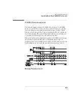
Minimum transitions stored
The figure above shows what data is stored from a data stream with
transitions that occur at a slow rate (more than 24 ns apart).
As shown, transitions are stored in two different ways, depending
strictly on chance. Remember that the transition detector only looks at
the full 34 bits while the data is stored as two 17-bit samples. So, the
transition detector will not see time tag 3 (101/000) as a transition.
However, when the detector compares the transition to time tags 2
(101/101) or 4 (000/000), it sees a difference and detects them as
transitions. For this first set of time tags, the transition detector sees
more transitions than are really there. This causes the analyzer to store
6 samples per transition (three 34-bit sample pairs), instead of just
two, as in the 125-MHz mode. If all of the transitions will be stored in
this way throughout the trace, the minimum number of stored
transitions is 682 (4096/6).
However, as you see with time tags 7 (000/000) and 8 (001/001),
transitions can fall between the pairs of samples. When this happens,
only one transition is detected and only 4 samples (two sample pairs)
are stored. If all transitions will be stored in this way, 1023 (4096/4)
transitions are stored.
From run to run, the actual number of transitions stored for transitions
that occur at a slower rate will fall between these two numbers, based
on the probability of a transition falling between a sample pair or falling
within a sample pair.
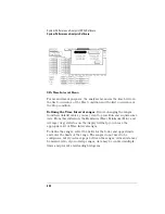
Summary of Contents for 1670E Series
Page 6: ...6 In This Book...
Page 26: ...26 Contents...
Page 27: ...27 Section 1 Logic Analyzer...
Page 28: ...28...
Page 29: ...29 1 Logic Analyzer Overview...
Page 39: ...39 2 Connecting Peripherals...
Page 49: ...49 3 Using the Logic Analyzer...
Page 72: ...72 Using the Logic Analyzer The Inverse Assembler...
Page 73: ...73 4 Using the Trigger Menu...
Page 101: ...101 5 Using the Oscilloscope...
Page 151: ...151 6 Using the Pattern Generator...
Page 199: ...199 7 Triggering Examples...
Page 237: ...237 8 File Management...
Page 249: ...249 9 Logic Analyzer Reference...
Page 360: ...360 Logic Analyzer Reference The Compare Menu...
Page 361: ...361 10 System Performance Analysis SPA Software...
Page 397: ...397 11 Logic Analyzer Concepts...
Page 430: ...430 Logic Analyzer Concepts The Analyzer Hardware Oscilloscope board theory Oscilloscope board...
Page 439: ...439 12 Troubleshooting the Logic Analyzer...
Page 455: ...455 13 Specifications...
Page 471: ...471 14 Operator s Service...
Page 479: ...479 Operator s Service Troubleshooting Troubleshooting Flowchart 2...
Page 491: ...491 Section 2 LAN...
Page 492: ...492...
Page 493: ...493 15 Introducing the LAN Interface...
Page 497: ...497 16 Connecting and Configuring the LAN...
Page 506: ...506 Connecting and Configuring the LAN Connecting and Configuring the LAN...
Page 507: ...507 17 Accessing the Logic Analyzer File System Using the LAN...
Page 515: ...515 18 Using the LAN s X Window Interface...
Page 527: ...527 19 Retrieving and Restoring Data Using the LAN...
Page 539: ...539 20 Programming the Logic Analyzer Using the LAN...
Page 546: ...546 Programming the Logic Analyzer Using the LAN Programming the Logic Analyzer Using the LAN...
Page 547: ...547 21 LAN Concepts...
Page 555: ...555 22 Troubleshooting the LAN Connection...
Page 580: ...580 Troubleshooting the LAN Connection Getting Service Support...
Page 581: ...581 Section 3 Symbol Utility...
Page 582: ...582...
Page 583: ...583 23 Symbol Utility Introduction...
Page 588: ...588 Symbol Utility Introduction Symbol Utility Introduction...
Page 589: ...589 24 Getting Started with the Symbol Utility...
Page 597: ...597 25 Using the Symbol Utility...
Page 609: ...609 26 Symbol Utility Features and Functions...


