


181
Using the Pattern Generator
Building Test Vectors and Macros
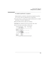
When deleting vector rows, the INIT START, INIT END, MAIN START,
and MAIN END cannot be deleted. Deleting all the vector rows from
INIT START to MAIN END will reset the sequence to the powerup
state. The deletion will not be performed if the results of the delete
operation will place fewer than two vectors in the main sequence, or, if
the delete operation will place an instruction on any of the following
vectors:
•
The first vector of the INIT sequence.
•
The first vector of the MAIN sequence.
•
The last vector of the MAIN sequence.
•
The vector prior to the IF block.
•
The first vector of the IF block.
•
The last vector of the IF block.
•
The vector following the IF block.
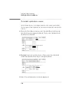
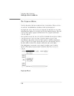
Merge
Selecting the Merge field brings up a pop-up menu that lets you select
sections of a previously created configuration file to merge after the
current line in the sequence. The Input Drive field selects between the
hard disk or the front floppy disk (if present). The Filename field
displays a file browser pop-up menu that allows searching for the file to
be used in the merge. The Merge Section field lets you select the
section of the configuration to be merged. Configuration sections
consist of the main sequence and any macros that were created. The
merge will not be performed in the following cases:
•
Merge data exceeds the maximum number of sequence lines.
•
Merge data requires more repeats than are available.
•
Merge data requires more macro calls than are available.
Summary of Contents for 1670E Series
Page 6: ...6 In This Book...
Page 26: ...26 Contents...
Page 27: ...27 Section 1 Logic Analyzer...
Page 28: ...28...
Page 29: ...29 1 Logic Analyzer Overview...
Page 39: ...39 2 Connecting Peripherals...
Page 49: ...49 3 Using the Logic Analyzer...
Page 72: ...72 Using the Logic Analyzer The Inverse Assembler...
Page 73: ...73 4 Using the Trigger Menu...
Page 101: ...101 5 Using the Oscilloscope...
Page 151: ...151 6 Using the Pattern Generator...
Page 199: ...199 7 Triggering Examples...
Page 237: ...237 8 File Management...
Page 249: ...249 9 Logic Analyzer Reference...
Page 360: ...360 Logic Analyzer Reference The Compare Menu...
Page 361: ...361 10 System Performance Analysis SPA Software...
Page 397: ...397 11 Logic Analyzer Concepts...
Page 430: ...430 Logic Analyzer Concepts The Analyzer Hardware Oscilloscope board theory Oscilloscope board...
Page 439: ...439 12 Troubleshooting the Logic Analyzer...
Page 455: ...455 13 Specifications...
Page 471: ...471 14 Operator s Service...
Page 479: ...479 Operator s Service Troubleshooting Troubleshooting Flowchart 2...
Page 491: ...491 Section 2 LAN...
Page 492: ...492...
Page 493: ...493 15 Introducing the LAN Interface...
Page 497: ...497 16 Connecting and Configuring the LAN...
Page 506: ...506 Connecting and Configuring the LAN Connecting and Configuring the LAN...
Page 507: ...507 17 Accessing the Logic Analyzer File System Using the LAN...
Page 515: ...515 18 Using the LAN s X Window Interface...
Page 527: ...527 19 Retrieving and Restoring Data Using the LAN...
Page 539: ...539 20 Programming the Logic Analyzer Using the LAN...
Page 546: ...546 Programming the Logic Analyzer Using the LAN Programming the Logic Analyzer Using the LAN...
Page 547: ...547 21 LAN Concepts...
Page 555: ...555 22 Troubleshooting the LAN Connection...
Page 580: ...580 Troubleshooting the LAN Connection Getting Service Support...
Page 581: ...581 Section 3 Symbol Utility...
Page 582: ...582...
Page 583: ...583 23 Symbol Utility Introduction...
Page 588: ...588 Symbol Utility Introduction Symbol Utility Introduction...
Page 589: ...589 24 Getting Started with the Symbol Utility...
Page 597: ...597 25 Using the Symbol Utility...
Page 609: ...609 26 Symbol Utility Features and Functions...


