


61
Using the Logic Analyzer
Using the Analyzer Menus
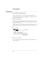
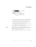
To examine an analyzer waveform
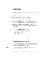
The Analyzer Waveform menu lets you view state or timing data in a
format similar to an oscilloscope display. The horizontal axis represents
states (in state mode) or time (in timing mode) and the vertical axis
represents logic highs and lows.
1
In Analyzer mode, press the Run key to acquire data.
In any mode other than Analyzer, Scope, or Patt Gen, pressing the Run
key has no effect. The menus which ignore Run lack the Run field
onscreen. In Analyzer mode with Run available, the menu changes to a
display menu.
2
Go to the Analyzer Waveform menu.
3
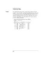
To adjust the horizontal axis (sec/Div or states/Div), use the
knob.
If nothing happens when you turn the knob, make sure the Div field has
a roll indicator above it, as in the figures on the next page. When you
first enter the Waveform menu, the knob adjusts the horizontal axis but
if you select another rollable field, the knob will control that field
instead.
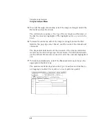
4
To adjust the display relative to the trigger, select the Delay field
and enter a value or use the knob.
The portion of memory being displayed is indicated by a white bar
along the bottom of the display area. The position of the trigger in
memory is indicated by a red dot on the same line. When the bar
includes the dot, then the trigger is visible on the display as indicated
by a vertical line with a "t" underneath.
Summary of Contents for 1670E Series
Page 6: ...6 In This Book...
Page 26: ...26 Contents...
Page 27: ...27 Section 1 Logic Analyzer...
Page 28: ...28...
Page 29: ...29 1 Logic Analyzer Overview...
Page 39: ...39 2 Connecting Peripherals...
Page 49: ...49 3 Using the Logic Analyzer...
Page 72: ...72 Using the Logic Analyzer The Inverse Assembler...
Page 73: ...73 4 Using the Trigger Menu...
Page 101: ...101 5 Using the Oscilloscope...
Page 151: ...151 6 Using the Pattern Generator...
Page 199: ...199 7 Triggering Examples...
Page 237: ...237 8 File Management...
Page 249: ...249 9 Logic Analyzer Reference...
Page 360: ...360 Logic Analyzer Reference The Compare Menu...
Page 361: ...361 10 System Performance Analysis SPA Software...
Page 397: ...397 11 Logic Analyzer Concepts...
Page 430: ...430 Logic Analyzer Concepts The Analyzer Hardware Oscilloscope board theory Oscilloscope board...
Page 439: ...439 12 Troubleshooting the Logic Analyzer...
Page 455: ...455 13 Specifications...
Page 471: ...471 14 Operator s Service...
Page 479: ...479 Operator s Service Troubleshooting Troubleshooting Flowchart 2...
Page 491: ...491 Section 2 LAN...
Page 492: ...492...
Page 493: ...493 15 Introducing the LAN Interface...
Page 497: ...497 16 Connecting and Configuring the LAN...
Page 506: ...506 Connecting and Configuring the LAN Connecting and Configuring the LAN...
Page 507: ...507 17 Accessing the Logic Analyzer File System Using the LAN...
Page 515: ...515 18 Using the LAN s X Window Interface...
Page 527: ...527 19 Retrieving and Restoring Data Using the LAN...
Page 539: ...539 20 Programming the Logic Analyzer Using the LAN...
Page 546: ...546 Programming the Logic Analyzer Using the LAN Programming the Logic Analyzer Using the LAN...
Page 547: ...547 21 LAN Concepts...
Page 555: ...555 22 Troubleshooting the LAN Connection...
Page 580: ...580 Troubleshooting the LAN Connection Getting Service Support...
Page 581: ...581 Section 3 Symbol Utility...
Page 582: ...582...
Page 583: ...583 23 Symbol Utility Introduction...
Page 588: ...588 Symbol Utility Introduction Symbol Utility Introduction...
Page 589: ...589 24 Getting Started with the Symbol Utility...
Page 597: ...597 25 Using the Symbol Utility...
Page 609: ...609 26 Symbol Utility Features and Functions...


