


369
System Performance Analysis (SPA) Software
System Performance Analysis Software
SPA measurement processes
This section introduces you to the measurement processes of the
System Performance Analysis (SPA) software. It tells you how to select
the appropriate trace mode and labels. It also explains how SPA
samples and sorts data.
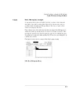
Selecting and changing trace modes
SPA has three trace modes: State Overview, State Histogram, and Time
Interval. These are selected by the Trace Mode field in the SPA data
display.
Only the currently displayed trace mode is affected during an
acquisition. While acquiring and viewing data in one trace mode, the
other two trace modes are not updated. If the trace mode or any other
critical variable is changed during an acquisition, the logic analyzer
stops the acquisition and displays "Warning: Run HALTED due to
variable change."
Each trace mode only performs statistics on its own database.
Therefore, if acquisitions are completed in two different trace modes,
the two modes will not contain the same data.
For example, you select the State Overview mode and press the Run
key. After the data accumulates for a period, press Stop. You then
select the Time Interval mode and the screen is blank since no data has
been acquired in this mode. You again press Run, and let data
accumulate and press Stop. In this example, two separate data sets are
acquired, the first for State Overview mode, the second for Time
Interval. You can now move between the modes and see the correct
data for the associated measurement.
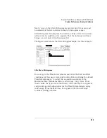
This separate acquisition data applies to all three trace modes. In this
way, three separate views of the target system can be acquired and
stored in SPA.
Summary of Contents for 1670E Series
Page 6: ...6 In This Book...
Page 26: ...26 Contents...
Page 27: ...27 Section 1 Logic Analyzer...
Page 28: ...28...
Page 29: ...29 1 Logic Analyzer Overview...
Page 39: ...39 2 Connecting Peripherals...
Page 49: ...49 3 Using the Logic Analyzer...
Page 72: ...72 Using the Logic Analyzer The Inverse Assembler...
Page 73: ...73 4 Using the Trigger Menu...
Page 101: ...101 5 Using the Oscilloscope...
Page 151: ...151 6 Using the Pattern Generator...
Page 199: ...199 7 Triggering Examples...
Page 237: ...237 8 File Management...
Page 249: ...249 9 Logic Analyzer Reference...
Page 360: ...360 Logic Analyzer Reference The Compare Menu...
Page 361: ...361 10 System Performance Analysis SPA Software...
Page 397: ...397 11 Logic Analyzer Concepts...
Page 430: ...430 Logic Analyzer Concepts The Analyzer Hardware Oscilloscope board theory Oscilloscope board...
Page 439: ...439 12 Troubleshooting the Logic Analyzer...
Page 455: ...455 13 Specifications...
Page 471: ...471 14 Operator s Service...
Page 479: ...479 Operator s Service Troubleshooting Troubleshooting Flowchart 2...
Page 491: ...491 Section 2 LAN...
Page 492: ...492...
Page 493: ...493 15 Introducing the LAN Interface...
Page 497: ...497 16 Connecting and Configuring the LAN...
Page 506: ...506 Connecting and Configuring the LAN Connecting and Configuring the LAN...
Page 507: ...507 17 Accessing the Logic Analyzer File System Using the LAN...
Page 515: ...515 18 Using the LAN s X Window Interface...
Page 527: ...527 19 Retrieving and Restoring Data Using the LAN...
Page 539: ...539 20 Programming the Logic Analyzer Using the LAN...
Page 546: ...546 Programming the Logic Analyzer Using the LAN Programming the Logic Analyzer Using the LAN...
Page 547: ...547 21 LAN Concepts...
Page 555: ...555 22 Troubleshooting the LAN Connection...
Page 580: ...580 Troubleshooting the LAN Connection Getting Service Support...
Page 581: ...581 Section 3 Symbol Utility...
Page 582: ...582...
Page 583: ...583 23 Symbol Utility Introduction...
Page 588: ...588 Symbol Utility Introduction Symbol Utility Introduction...
Page 589: ...589 24 Getting Started with the Symbol Utility...
Page 597: ...597 25 Using the Symbol Utility...
Page 609: ...609 26 Symbol Utility Features and Functions...


