


269
Logic Analyzer Reference
Probing
Oscilloscope probes
The two oscilloscope probes supplied with the logic analyzer are
HP 1160A Miniature Passive Probes. These small, lightweight probes
allow measurements that were previously very difficult in densely
populated circuits.
For complete information on the operation, maintenance, and
adjustments of the miniature passive probes, be sure to read the
operating note that is packaged with the probes.
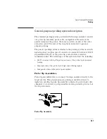
Probe Inputs
Probe inputs are located on the front panel to the right of the power
switch. Input 1 is on the left. The probes may be connected directly to
the BNC input connectors. The signal is dc-coupled to the oscilloscope.
BNC cables can be connected directly to the BNC connectors. A BNC-
to BNC cable is not provided with the instrument, but you can order it
separately.
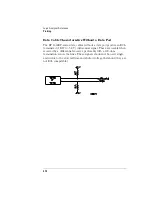
Maximum Probe Input Voltage
The maximum input voltage of each logic analyzer probe is ±40 volts
peak. The maximum input voltage of the oscilloscope is ±250 volts dc
at 1 M
Ω
setting and 5 volts rms at 50
Ω
setting.
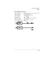
Calibration Outputs
There is one calibration output BNC located on the rear panel. It is the
AC/DC calibration signal source. This signal is used during calibration
of the oscilloscope. This calibration signal can also be used for probe
compensation adjustment.
Summary of Contents for 1670E Series
Page 6: ...6 In This Book...
Page 26: ...26 Contents...
Page 27: ...27 Section 1 Logic Analyzer...
Page 28: ...28...
Page 29: ...29 1 Logic Analyzer Overview...
Page 39: ...39 2 Connecting Peripherals...
Page 49: ...49 3 Using the Logic Analyzer...
Page 72: ...72 Using the Logic Analyzer The Inverse Assembler...
Page 73: ...73 4 Using the Trigger Menu...
Page 101: ...101 5 Using the Oscilloscope...
Page 151: ...151 6 Using the Pattern Generator...
Page 199: ...199 7 Triggering Examples...
Page 237: ...237 8 File Management...
Page 249: ...249 9 Logic Analyzer Reference...
Page 360: ...360 Logic Analyzer Reference The Compare Menu...
Page 361: ...361 10 System Performance Analysis SPA Software...
Page 397: ...397 11 Logic Analyzer Concepts...
Page 430: ...430 Logic Analyzer Concepts The Analyzer Hardware Oscilloscope board theory Oscilloscope board...
Page 439: ...439 12 Troubleshooting the Logic Analyzer...
Page 455: ...455 13 Specifications...
Page 471: ...471 14 Operator s Service...
Page 479: ...479 Operator s Service Troubleshooting Troubleshooting Flowchart 2...
Page 491: ...491 Section 2 LAN...
Page 492: ...492...
Page 493: ...493 15 Introducing the LAN Interface...
Page 497: ...497 16 Connecting and Configuring the LAN...
Page 506: ...506 Connecting and Configuring the LAN Connecting and Configuring the LAN...
Page 507: ...507 17 Accessing the Logic Analyzer File System Using the LAN...
Page 515: ...515 18 Using the LAN s X Window Interface...
Page 527: ...527 19 Retrieving and Restoring Data Using the LAN...
Page 539: ...539 20 Programming the Logic Analyzer Using the LAN...
Page 546: ...546 Programming the Logic Analyzer Using the LAN Programming the Logic Analyzer Using the LAN...
Page 547: ...547 21 LAN Concepts...
Page 555: ...555 22 Troubleshooting the LAN Connection...
Page 580: ...580 Troubleshooting the LAN Connection Getting Service Support...
Page 581: ...581 Section 3 Symbol Utility...
Page 582: ...582...
Page 583: ...583 23 Symbol Utility Introduction...
Page 588: ...588 Symbol Utility Introduction Symbol Utility Introduction...
Page 589: ...589 24 Getting Started with the Symbol Utility...
Page 597: ...597 25 Using the Symbol Utility...
Page 609: ...609 26 Symbol Utility Features and Functions...


