


349
Logic Analyzer Reference
The Mixed Display Menu
The Mixed Display Menu
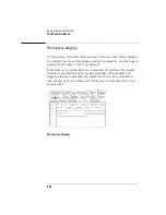
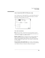
The Mixed Display menu combines a state listing display located at the
top of the menu and a waveform display located at the bottom of the
menu. The Mixed Display menu shows both state and timing data in the
same display.
The Mixed Display menu only becomes available when at least one
analyzer is configured as a state analyzer, with its Count field in the
Trigger menu set to Time. If two state analyzers are configured, both
state listing displays can be interleaved as well as shown separately,
however, the listing menus are the best display menus for a two-state
analyzer configuration.
The waveform display area shows timing analyzer waveforms from the
configured timing analyzer, the oscilloscope waveform
(1660ES-series), or both.
Interleaving state listings
Interleaved state listings lets you view two labels and their data from
different analyzers in the same column. The process of interleaving
state listings can be performed in either the Listing menu or the Mixed
Display menu. For example, if data is interleaved in the Listing menu, it
will be automatically interleaved in the Mixed Display menu.
The interleaved label is placed directly above the selected label, and all
interleaved data is displayed in yellow. In addition, the state numbers
of the interleaved data are indented to the right. Because of the lack of
room available in the listing portion of the Mixed Display menu, the
label identifying the interleaved data is not displayed. For this reason,
when two state analyzers are configured the listing menus should be
used to display interleaved labels.
Summary of Contents for 1670E Series
Page 6: ...6 In This Book...
Page 26: ...26 Contents...
Page 27: ...27 Section 1 Logic Analyzer...
Page 28: ...28...
Page 29: ...29 1 Logic Analyzer Overview...
Page 39: ...39 2 Connecting Peripherals...
Page 49: ...49 3 Using the Logic Analyzer...
Page 72: ...72 Using the Logic Analyzer The Inverse Assembler...
Page 73: ...73 4 Using the Trigger Menu...
Page 101: ...101 5 Using the Oscilloscope...
Page 151: ...151 6 Using the Pattern Generator...
Page 199: ...199 7 Triggering Examples...
Page 237: ...237 8 File Management...
Page 249: ...249 9 Logic Analyzer Reference...
Page 360: ...360 Logic Analyzer Reference The Compare Menu...
Page 361: ...361 10 System Performance Analysis SPA Software...
Page 397: ...397 11 Logic Analyzer Concepts...
Page 430: ...430 Logic Analyzer Concepts The Analyzer Hardware Oscilloscope board theory Oscilloscope board...
Page 439: ...439 12 Troubleshooting the Logic Analyzer...
Page 455: ...455 13 Specifications...
Page 471: ...471 14 Operator s Service...
Page 479: ...479 Operator s Service Troubleshooting Troubleshooting Flowchart 2...
Page 491: ...491 Section 2 LAN...
Page 492: ...492...
Page 493: ...493 15 Introducing the LAN Interface...
Page 497: ...497 16 Connecting and Configuring the LAN...
Page 506: ...506 Connecting and Configuring the LAN Connecting and Configuring the LAN...
Page 507: ...507 17 Accessing the Logic Analyzer File System Using the LAN...
Page 515: ...515 18 Using the LAN s X Window Interface...
Page 527: ...527 19 Retrieving and Restoring Data Using the LAN...
Page 539: ...539 20 Programming the Logic Analyzer Using the LAN...
Page 546: ...546 Programming the Logic Analyzer Using the LAN Programming the Logic Analyzer Using the LAN...
Page 547: ...547 21 LAN Concepts...
Page 555: ...555 22 Troubleshooting the LAN Connection...
Page 580: ...580 Troubleshooting the LAN Connection Getting Service Support...
Page 581: ...581 Section 3 Symbol Utility...
Page 582: ...582...
Page 583: ...583 23 Symbol Utility Introduction...
Page 588: ...588 Symbol Utility Introduction Symbol Utility Introduction...
Page 589: ...589 24 Getting Started with the Symbol Utility...
Page 597: ...597 25 Using the Symbol Utility...
Page 609: ...609 26 Symbol Utility Features and Functions...


