background image

Stay ahead. With Agfa Global Services. 

:Anapurna M

4F

 - Operator Manual 

Information - Printer overview 

9

2. Printer overview.

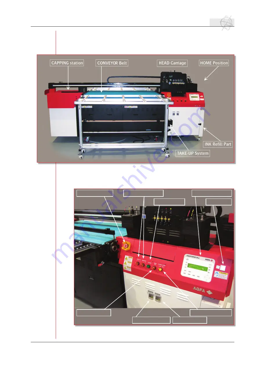
2.1 

Front view, parts & locations.

The roll to roll system is optional for the :Anapurna M4f

and is not delivered with a standard system.

2.2 

Home view, parts & locations.

EMERGENCY Stop

UV LAMP R-L Switch

LCD Operation Panel

Start Button

Sub Ink Tank Temp.

Head Base Temp.

Vacuum Switch

Capping Cover Switch

Media Set

Summary of Contents for ANAPURNA M4F

Page 1: ...ab Operator Manual Anapurna M4F FW version 1 979 Stay ahead with Agfa Global Services Operator Manual ...

Page 2: ...a M4F Operator Manual FW version 1 979 rev 20080808 Any remarks and or suggestions on the content of this operator manual can be send to dieter jancart agfa com rashed chughtai agfa com Agfa Graphics NV Belgium ...

Page 3: ...s 14 d Left tabs 14 2 2 Open an image 15 2 3 Cropping resizing an image 15 a Resizing 15 b Cropping 15 c Restore Original View 16 d Rotating 16 e Mirroring 17 2 4 Choosing an imaging configuration 17 2 5 Ripping and printing the image 17 3 The operator panel general overview 19 4 Start up Shutdown Procedures 20 4 1 Start up Procedure 20 4 2 Making the engine ready for Printing 20 4 3 Shutdown Proc...

Page 4: ...the Encoder Strip 47 3 9 Maintenance on input Air Filter 47 3 10 Lubricating the Carriage Rails 48 3 11 Greasing the Carriage Bearing Blocks 48 3 12 Checking the UV Lamps 49 3 13 Replacing the UV Lamps 49 3 14 Cleaning the UV Lamps Crystal Glass 50 3 15 Power Shut Down or Compressor Break Down Procedures 51 3 16 Bleeding the ink filters 51 3 17 Replacing the air filters 52 4 Periodic Maintenance 5...

Page 5: ...er always im plies that you must be aware of the harm that the U V radiation and the U V inks can cause 1 1 Warning labels The printer has labels that give simple explanations of operations that require particu lar care Read and understand the contents of these labels thouroughly before performing your work Moving parts can crush and cut Keep guards in place Lock out power before servicing UV Ligh...

Page 6: ... sensors and therefore will not stop when it runs into an obstacle like media or body parts The Anapurna M4F4F is equiped with optical sensors around the working path of the shuttle On each of the four corners of the engine you will see a metal tower construction containing two optical sensor assemblies each If the optical light path gets obstructed the shuttle will stop at its current position an...

Page 7: ...rn and irritation will be the consequence when e g your hands have direct contact with the radiation Don t look directly into the U V light this will damage your eye sight If you need to look in the direction of the U V light make sure that you wear protective glasses a Detail of the UV light UV lamps emit not only ultraviolet light but also visible light and wavelengths in the infrared spectrum I...

Page 8: ... like saw dust to clean Little amounts of spilled ink can be cleaned using a cloth Don t forget to treat the saw dust and cloths as chemical waste uncured inks The shelf life of the Anapurna M4F inks is 12 months the expiry date is mentioned on each bottle Ideal stor age of inks is between 4 10 C the temperature should not exceed 25 C at any time a Curing Process Water based and solvent based inks...

Page 9: ...view 2 1 Front view parts locations The roll to roll system is optional for the Anapurna M4f and is not delivered with a standard system 2 2 Home view parts locations EMERGENCY Stop UV LAMP R L Switch LCD Operation Panel Start Button Sub Ink Tank Temp Head Base Temp Vacuum Switch Capping Cover Switch Media Set ...

Page 10: ...0 Information Printer overview 2 3 Capping station view parts locations 2 4 Head carriage view parts locations 2 5 Rearside view parts locations Main power switch Emergency stop Vacuum switch Media Set Vacuum valves UV Lamps Print heads Ink solution valves Purge switch ...

Page 11: ...rint unit on top right side of the main win dow Agfa is suporting two quality modes 720x720 dpi or 720x1440 dpi Close the setup window and choose the rip icon on the main window or via rip only in the print menu The image will be ripped and it will be placed in the print queue 1 2 Starting up the Anapurna M4F When the Anapurna M4F is in a normal shutdown mode overnight standstill the shuttle will ...

Page 12: ... head height Press Enter a second time to lower the shuttle to the head gap distance Move the shuttle back to the home position by pressing Enter The head gap proce dure is now completed and the shuttle is set to the desired distance Check the state of the print heads by performing a prime print Turn on the U V lamps and press F1 in the main menu The lamps start warming up and after 90 sec the Ana...

Page 13: ...onal settings Image The Image menu contains tools for modifying the image currently open in the Job tab or currently selected in the Layout tab Color The Color menu contains key SoftRIP color tools for managing spot col ors color gamut correction curves etc Print Access to printer and Imaging Configuration set up RIP processing op tions and job queues Page When active enables switching among diffe...

Page 14: ... or job to be prepared for printing With the Job tab selected a full set of options for sizing cropping scaling and tiling appear Layout Tab When the Layout tab is selected you use the full width of your media as a digital canvas upon which you can prepare images to print as part of your complete production run With this workflow you can easily drag and drop images into the layout manipulate them ...

Page 15: ...iling feature Computing Scaling Percentage Automatically SoftRIP will size an image if you enter the desired width or length of the final print in either the Width or Height windows in the Output area For example you can enter the printable width of your print media or one dimension of a light box or display hard ware Make sure the Constrain Proportions box to the left of the Width and Height boxe...

Page 16: ...he windows labeled Left and Bottom in the Crop area The numbers shown represent the distance in inches or centimeters mea sured from the respective edge of the original image to the outside border of the marquee Change the marquee position more precisely by hand entering new values in these windows When you enter new numbers to position the marquee the mar quee will not move until the ENTER or TAB...

Page 17: ... possible use of color management You can select the imaging configuration in the setup screen Launch the Setup screen from the Print menu at the top of the Main Screen In the drop down box of the imaging configuration you find 8 different print strategies AnapurnaM4F_Q4p_PSS_Absorbent AnapurnaM4F_Q4p_PSS_Absorbent_bi AnapurnaM4F_Q4p_PSS_NonAbsorbent AnapurnaM4F_Q4p_PSS_NonAbsorbent_bi AnapurnaM4F...

Page 18: ...rint menu The job will be RIP d and added to both the RIP and Print Queue listings on the Master Queues screen more below If you want to print you have to select the job in the print queue and hit the print button ADD TO RIP QUEUE To add a job to the RIP Queue to be RIP d later select ADD TO RIP QUEUE from the Print menu It will be added to the RIP Queue but not RIP d ...

Page 19: ...ne the LED will go out If you send a job when the engine is in the Off line status the LED will start blinking the job waits until you push the On line button 2 LED Indicates On Line or Off Line status 3 ESC Use this button to CANCEL a print and to RETURN from a menu 4 F1 F6 Function keys to access different menu s and settings 5 TEST Printing test F1 Prime F2 Vert Alignment F3 Hor Alignment 6 PUR...

Page 20: ...n if required close the Capping Cover Check The Vacuum Should be around 036 The Sub Ink Tank Head Base Temperature Approx 45 degrees 49 de grees respect 4 2 Making the engine ready for Printing Turn all the ink 2 way valves back to I Position ink position the extreme right hand side valve should already be at I position Make sure the Home Cover is in open Press the PURGE button 2 3 times and check...

Page 21: ...t Down Procedure The carriage is at the Home Position after printing It is better to check if all the print heads are in good shape by doing a Prime Test Turn the Lamps OFF Let the Lamps cool down wait for Lamp Fans to go off Make sure that there is plenty of Cleaning Solution in the Main Tank and an ex tra 1 litre bottle in stock Perform a Head Flush on all the print heads Open the Home Cover Swi...

Page 22: ...apping Cover clean the capping station Press CAPPING from the control panel the carriage will start going up move towards the left side capping side move down on the caps Push the Red Emergency Button Turn the Power Switch OFF from rear side of the Anapurna Turn the Mains of the premises OFF Turn the Compressor Drier OFF ...

Page 23: ... vaule that is too low will make different passes overlap each other This results in dark lines in your print If you want to check the feed adjust press F1 to enter the feed calibration menu Select F2 to start the print In the first pass the printer will print 2x 4 lines of every color Every pass that follows a new line will be printed besides one of the first 4 In case that the printed lines are ...

Page 24: ...l and only the block with the correct setting will show three lines In all the other blocks and values you will see 6 lines per color and per firing row 3 lines are printed from left to right 3 lines are printed from right to left Choose the correct value for every color and every nozzle row and enter these values into the dir adjust window Make sure that you always check the bi directional alignm...

Page 25: ... to set the shuttle to the cor rect height Press the left arrow to move the shuttle to the desired position Make sure that you position the shuttle so the height calibration will be done between the two red dots on the beam When the shuttle is in position press En ter and the shuttle will lower itself to the reference height This is a default value and is not the same as the actual head height Pre...

Page 26: ... Anapurna M4F Operator Manual Stay ahead With Agfa Global Services 5 7 Importance of the bi directional alignment 26 Operations Setting up the Anapurna M ...

Page 27: ...rations Setting up the Anapurna M 27 A correct bi directional alignment is crucial for an accurate dot placement The bi directional alginment is depending on the shuttle speed and the head gap Whenever one of those changes the bi directional alginment needs to be checked ...

Page 28: ...o right Q4P The number of passes are related to quality mode that was selected It are the number of passes that the shuttle needs to complete one printing line 720 dpi Q4P 1440 dpi Q8P S10 The speed of the shuttle can be changed by a value between 1 slow and 10 fast The default setting S10 is the most optimized speed Decreasing the speed will not provide better quality and will only limit your pro...

Page 29: ...ER By pressing F2 you enter the panel which controls the u v lamps settings The bottom line shows you the burning hours of the u v lamps This counter can be resetted only by a service engineer The other settings can be changed by using the arrows on the control panel Pressing left or right will make the cursor move between the different pa rameters Pressing up or down will change the value of that...

Page 30: ...nables you to delay the point where the shutter of the lamps opens and closes The value is expressed in centimeters and ranges from 0 to 99 F3 HOME COVER By pressing F3 the home cover protection plate slide backwards This gives you easy access underneath the print heads F4 CLEANING IP SET The cleaning ip set window contains information and parameters about safety network connection and the capping...

Page 31: ...ion of the motor roller defining the way motor will turn When the mode is set to manual you can move the roll to roll system by using the function keys F2 F3 F5 F6 Press and hold down the key for as long as you want the motor to rotate F2 FRONT CW the front motor will turn clock wise F3 FRONT CCW the front motor will turn counter clock wise F5 REAR CW the rear motor will turn clock wise F6 REAR CC...

Page 32: ...apacity F SPEED 1 to 5 default 1 The feed speed setting is the speed which the conveyor will move forward between printing passes This value can be changed between 1 slow and 5 fast If the shuttle starts to print the next pass when the conveyor belt is still moving you should increase the speed of the belt UNIT MM INCH You can choose between millimetres or inches and change the units of the margin...

Page 33: ...o roll The Anapurna M4F offers you the choice between handling rigids or roll media You can print one or more rigids at the same time or use the automatic winder and un winder system for roll fed media a Rigid media The media set bar will help you to position the rigids on the printing table Lower the media set bar by turning the media set switch front or rear side at the home position When you us...

Page 34: ...on the right spot Push the online button and the printer is ready to print b Roll media roll to rol sytem is optional If you work with roll media you can use the auto feed system of the Anapurna M4F It contains two tension bars a front and rear roll bar and a media roll bar The tension bars prevent distortion and waves on the media by applying a constant tension The rear roll bar will unwind the m...

Page 35: ...ll it hangs in loop blocking the beam of the optical sensor Position the rear tension bar and make sure that it is positioned horizontal to keep an even media tension Go to the front of the engine switch of the vacuum and pull the media so you can attach it to the rewind er system The media has to be aligned with the side of the conveyor belt so it will run straight Mount your media on the front r...

Page 36: ...These valves are po sitioned underneath the capping station access is through the side door Valve 1 controls the part of the table at the right side home position valve 2 is connected to the left side purge position Depending on the position and size of the media the vacuum can be controlled through these valves If the media only covers one of the two parts of the vacuum table e g vacuum 1 the suc...

Page 37: ...t blocks Every block shows you a certain quality and resolution setting or a certain nozzles that are being fired 1 2 Prime2 F2 Make sure that a left margin p 32 is set before you do a prime test The prime2 test looks like follows Two blocks are printed per color The first block is a solid block showing you the physi cal resolution that is printed in one pass 360 x 360 dpi The second block is buil...

Page 38: ...s a quick test to check the bi directional allignment of your shuttle It will print 15 lines per color from right to left and from left to right Per block you will have to see 15 clear lines If they start looking double and you can count 30 lines the bi directional setting is not correct Adjusting the bi directional allignment is discussed in Section B 5 5 The F5 function will print the bi directi...

Page 39: ...elt touches this device it should be realigned Procedure Loosen the conveyor belt Remove the metal covers on the backside both left and right completely unscrew left and right bolt Position the conveyor belt The belt s joint need to be positioned in the middle underneath the printing table Measure the distance on the left right side of the printing table start vs end of the conveyor belt This meas...

Page 40: ...the measured difference on the side where belt was moving from Transport test Move conveyor belt for at least 10 minutes Check marks on belt and printing table If needed adjust position of belt The position of the belt should not move more then 2mm Rotate the bolts at the REAR stand to CW or CCW to control the tension Those small adjust ments can be done while belt is moving Remark The position of...

Page 41: ...ger push A quick purge is an impulsive purge press and release the purge button very quick You press the purge button no longer than one second With a long purge you press the purge button for up to 3 seconds This is done to ensure that there is enough ink in the print heads If you purge too long the ink refill system will not be able to keep up This may result in air being intro duced in your sys...

Page 42: ...he print heads Close the solution valve by switching it to I Use a fibre free cloth to clean the heads by wiping them from back to front Refilling the flushed heads with ink again can be done with the purge procedure Make sure that only the flushed heads will be purged so switch all other valves to S Bleed negative pressure to 010 Bleeding the print heads is performed to get rid of any air in the ...

Page 43: ...e different components of the ink circuit ink tank pump filter energy chain sub ink tank 2 way valve print head The main ink tanks are located in the door on the right side of the printer Every ink tank can contain 1 6 liter of ink and has a low level detection at 0 3 liter When a low level is detected the engine will not print the next job until the empty tank is refilled The main ink tanks can b...

Page 44: ...se valves will allow you to switch between ink or solution that has to run to the print head They are used for cleaning the print heads or when you switch of the engine The print heads are mounted on a base plate which is also temperature con trolled The ideal temperature for the head base plate of the Anapurna M4F is 49 C A display on the right side of the printer home position shows you the actu...

Page 45: ... head base plate in a V shape every color having its own designated place b The negative pressure system The negative air pressure system is keeping the print heads from dripping Without this system the laws of gravity will make sure that the ink will flow out of the print heads and you will not be able to print The negative pressure is generated by a venturi system which converts positive pressur...

Page 46: ...n a waste tank This tank is lo cated inside the left compartment of the printer When the waste tank is almost full the control panel will dis play a warning You can drain it via the tap underneath the tank Make sure that the drained waste is processed as chem ical waste Don t mix the u v waste with solvent inks 3 7 Maintenance on Sub Air tank Over Flow Tank The sub air tank is the buffer which wil...

Page 47: ...orking well 3 8 Cleaning the Encoder Strip The encoder strip is the part that defines the x position of the carriage position of the firing pulse If the strip is dirty wrong signals will be sent to the shuttle resulting in printing artefacts The Encoder Strip is a transparent plastic strip located on top of the car riage beam To clean take a lint free cloth put some iso on the cloth and wipe the s...

Page 48: ...quantity should be mini mum The operator needs to make sure that when he feels the rail with his finger it should not be dry To lubricate the rail on the Home Side use the Carriage Release p 23 function 3 11 Greasing the Carriage Bearing Blocks Type of Grease Lithium Based or Urea Based JIS No 2 Application Quantity 1 5 to 2 0 gms approx per block Perform Lubricating the Carriage Rails procedures ...

Page 49: ... should be clear If it has turned white of dark yel low brown the lamps need replacement 3 13 Replacing the UV Lamps Tools Required 4 mm L key a small flat screw driver cotton gloves Parts Required 2 x E26XH UV Lamps for Anapurna M4F Power the engine down Power OFF by pushing in the Emer gency Button Make sure the lamps are not warm let the lamps cool down Remove the data connector going in the la...

Page 50: ...nder the lamp housing you can ac cess the glass as the carriage is at the top most posi tion Make sure the glass is clean if not you might need to use a scraper very gently to take out any ink residue To clean the glass from the inner side take the lamp assembly out of the housing as described in 3 13 Re placing the uv lamps Observe there are two pneumatic tubes going into the lamp housing at the ...

Page 51: ...the home position manually When the power is reinstated power the engine ON and perform a solution flush on all the print heads Purge the ink making sure all print heads have got rid of the solution Follow the procedures to do a Prime Test before printing a job b Compressor Break Down Make sure carriage is at home position Turn all the ink valves to S position Keep the Solution valve to I position...

Page 52: ... cable is not disconnected and you can still reach the manual feeding buttons Place some cleaning towels underneath the air filters Wear rubber gloves Loosen the white air cap on top of the filter Wait untill ink is coming out You can press the manual feeding button to speed up the process Tighten the white air cap Make sure that you clean up all the ink that came out 3 16 Replacing the air filter...

Page 53: ...hine oil Use Carriage Release function to clean the rails on the Home Side p 23 Clean the Encoder Strip with a clean lint free cloth p 47 You can use isopropyl alcohol Do not use Cleaning Solution or Solvents Use Carriage Release function to clean the Encoder Strip on the Home Side p 23 Check the sub air tank over flow tank for any ink p 46 Turn all the Ink Valves to S position Keep the Cleaning V...

Page 54: ...Button Turn the Power Switch OFF from rear side of the Anapurna At Restart start of the working week Power Switch to ON position Turn out the Emergency Button power on the engine pressing START Wait till the base plate temperature reaches 49 C Open the Home Cover Turn the Vacuum gauge to restore the negative vacuum to approx 036 Switch all the 2 way ink valves to I position leave the solution valv...

Page 55: ... till the base plate temperature reaches 49 C Open the Home Cover Turn the Vacuum gauge to restore the negative vacuum to approx 036 Switch all the 2 way ink valves to I position leave the solution valve at I Perform a Long Purge with intervals of 2 seconds ON and 4 seconds OFF till ink is coming out of the print heads Take a new lint free cloth and clean the ink residue from the print heads just ...

Page 56: ...eal between 4 10 C No more than 25 C at any time Shelf Life of inks Take care when filling the main ink tank cleaning tank Keep waste separate from the ink bottles Dispose off waste as per local council regulations Never mix solvent waste or aqueous waste with UV waste as per local council regulations 2 Printer Overview a Terminologies used Home Side Purge side or Capping side etc b Anapurna Shutt...

Page 57: ...p Head Height Calibration Left Top Margins Input output Support Tables UV Lamps Power settings Full Half and Mode settings Normal Both d Negative Pressure Settings C MAINTENANCE 1 Print Head Purging Cleaning Function of 2 way valve a Quick Purge if Prime Test nozzle test not good b Long Purge c Head Bleeding drop the negative pressure down to 010 d Head Cleaning using Cleaning Solution 2 Periodic ...

Page 58: ...illing the main ink tank cleaning tank Keep waste separate from the ink bottles Dispose off waste as per local council regulations Never mix solvent waste or aqueous waste with UV waste as per local council regulations 2 Printer Overview a Terminologies used Home Side Purge side or Capping side etc b Anapurna Shuttle carriage Layout Print Heads sub tanks etc 2 way ink valves solution valve UV Lamp...

Page 59: ...g Cancelling a print 4 Setting up the Anapurna M4F changing the parameters a Calibrating the engine Horizontal Alignment Bi Direction Alignment Step Size Feed Carriage Speed b Print Head Test Prime Menu F1 on Control Panel c Roll to roll print optional Media Loading Vacuum Settings on the bed Set Gap Head Height Calibration in regard to the media thickness Set Margins Parameters UV Lamps Power set...

Page 60: ... Periodic Maintenance a Daily Weekly Weekend Long Break engine preparation D MISCELLANEOUS 1 Consumables Required How to order a Inks Cleaning Solution b Recommended Media Appendix 3 Substrate list 2 Have you received the Operator Manual 3 Have you received the Anapurna M4F Ink MSDS 4 Have you printed samples on Anapurna engine using flexible rigid media 5 You are comfortable and you have received...

Page 61: ...y Back Paper Marchi Paper Coated Paper Banner Vinyl Seemee Backlit PVC Verseidag Self Adhesive Metamark MD5 PVC Metamark Vinyl Card Board Eclipse Opaque Paper Burgo IT White Liner Eska Screen Paper Kappa Attica Top Coated 1250g Display Board Foam PVC Board Forex Classic 3 mm PVC Alcan Airex Polypropylene Priplak Classic PP Pripalk Sheet Textile Textile Seemee light Polyester Verseidag Metal Plate ...

Page 62: ...cuum is available on the table allowing the media to feed properly Media Always check if the media is qualified compatible for UV inkjet printing Please con tact media supplier and ask questions Before printing check if the media is not damaged The rigid media should be able to sit flat on the table otherwise you will not be able to print head crashes Also handle the media in a way to avoid finger...

Reviews: