


22
System will then start turning steering axle slowly in both directions and measure speed at which it turns. It will regularly
increase speed at which it turns steering axle until it reaches maximum turning rate it measured at first part of this test. At
conclusion of calibration step, system will be able to know how fast it will turn steering axle at any signal strength it sends
to Steering Valve. When this step is complete, calibration procedure is complete.
Once Valve calibration process has completed, Save Calibration screen will appear.
Press
to accept and save calibration. Press
to discard all changes.
÷
NOTE!: If
is pressed, calibration will have to be restarted from beginning.
Mechanical Steering Unit
Vehicle types that use a mechanical device attached to steering wheel to control direction vehicle steers are calibrated
with this procedure. Almost any vehicle can be fitted with a mechanical steering unit. GCU must detect minimum current
that is required to start turning steering wheel as final step of calibration process. This step will perform a series of left and
right turns a differing turning rates.
MDU-G4 Deadband
—This step determines minimum current required to start turning steering wheel to the right and
to the left.
÷
NOTE!: Verify that engine RPM is at working speed while this part of calibration is taking place.
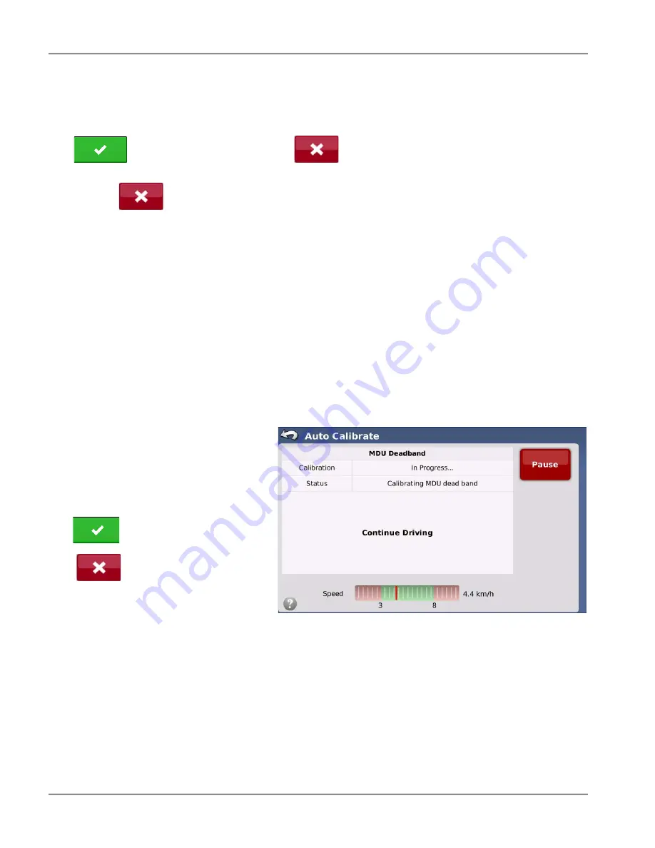
First part of test measures minimum current required to start turning steering wheel to right and to left. To begin
calibration, start driving vehicle in a straight line between 2.0 and 5.0 mph (3.2 and 8.0 k/h). Press Resume button to begin
calibration process.
Calibration process will perform a series of left and right turns at various rates of speed.
The calibration system determines the minimum
amount of effort required to turn wheel in either
direction and calibrates the rate of turn for specific
steering wheel positions.
Once MDU-G4 Deadband calibration process has
completed, Save Calibration screen will appear.
Press
to accept and save calibration.
Press
to discard all changes, and start
calibration from the beginning.
CAN Bus / ISO Controllers
Vehicle types that provide a CAN Bus or ISO Bus connection on machine to receive steering commands from the vehicle’s
steering controller are calibrated with this procedure. These vehicles have an angle sensor and steering valve from the
factory. These two components must be calibrated by vehicle manufacture so that vehicle can accurately determine
curvature it will travel at various angle sensor readings. Vehicle’s steering valve adjusts position of steering axle to get a
desired curvature independently of system.
To control these vehicles, system sends a desired curvature command to vehicle via CAN Bus. Vehicle then attempts to
adjust valve to match desired curvature. There can be some error to what vehicle thinks curvature is as compared to what
it actually is. This calibration step compares estimated curvature vehicle thinks it is using to actual curvature calculated by
GPS system. There is only one step to finish calibration.
Curvature
—This step compares estimated curvature from vehicle to true curvature as measured by GPS.
Next step of calibration process should start automatically from Common Calibration Steps.