


GeoSteer®
21
PN 2006410—ENG Rev. B
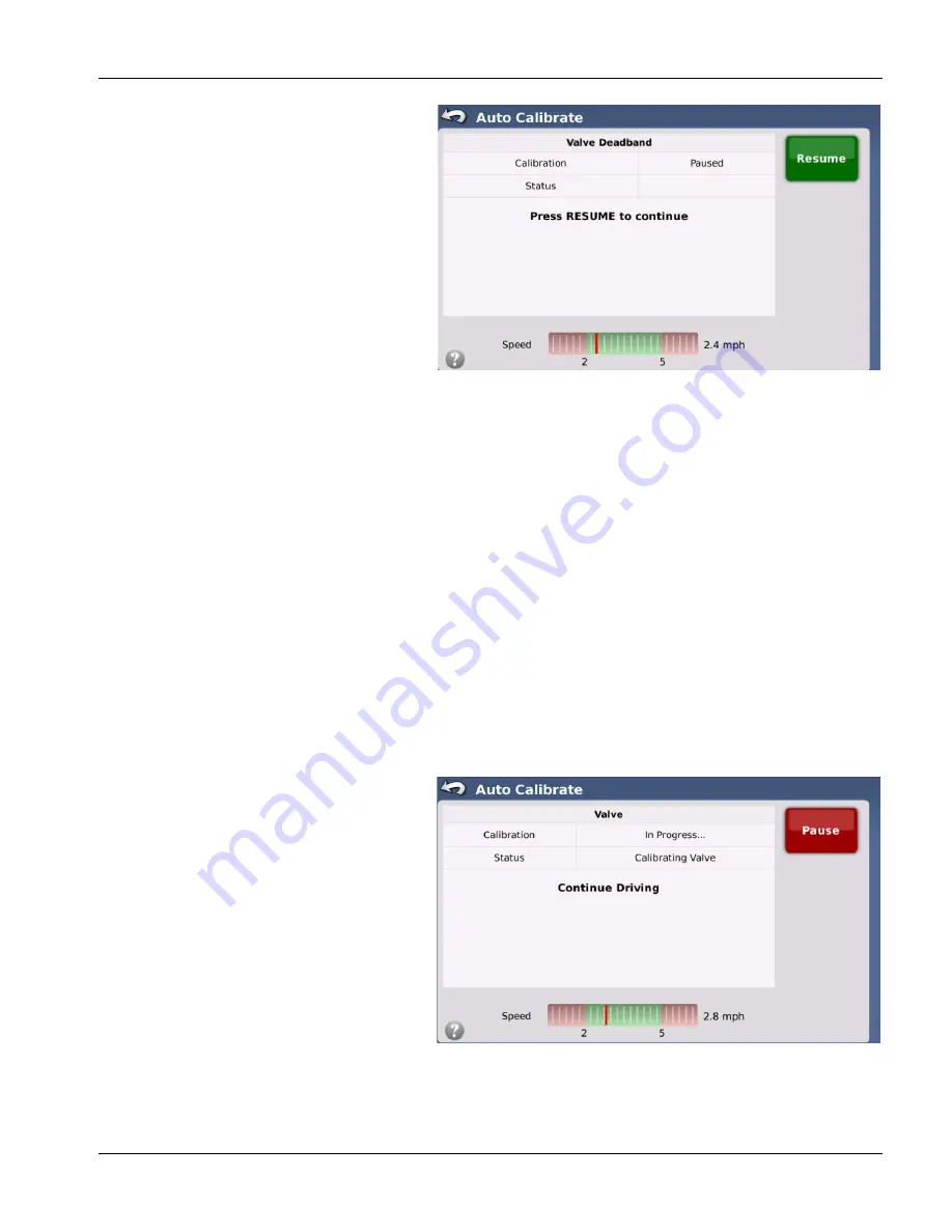
Valve Deadband
Oil flow is proportional to voltage or pulse width
signal changes sent from control unit. It takes a
certain minimum amount of signal to start oil flow
through valve. If signal is below that minimum
amount, no oil flows and steering axle will not
move. Voltages or pulse widths where there is no
valve movement is called Deadband. Deadband is
detected by incrementally increasing signal sent to
valve in both directions until Control Unit detects
motion from Wheel Angle Sensor.
To begin Valve Deadband calibration, drive vehicle
in a straight line between 2.0 and 5.0 mph (3.2 and
8.0 k/h) and then press Resume button to start
calibration process. Vehicle will continue to drive in
a straight line for a time. Eventually, steering axle
will begin to move to both sides. Once this
happens system will have determined deadband
for valve and move on to next step.
Angle Sensor
Control Unit reads value of Angle Sensor to determine position of steering. During calibration process, Control Unit holds
Angle Sensor at different positions from full left to full right and measures actual change of heading at each position using
the GPS antenna. At the conclusion of calibration, Control Unit can determine expected change of heading for any Angle
Sensor position. It is also able to determine exact Angle Sensor reading that should steer vehicle in a straight line.
÷
NOTE!: For next step in calibration process, vehicle will turn full left and full right. Make sure all objects are clear of
area where calibration is taking place.
Angle Sensor calibration should start automatically once Valve Deadband has been determined. If it does not, press
Resume button to start calibration process. Steering axle will make a hard turn to one direction and then back to opposite
direction to find maximum Angle Sensor stops. System will then reposition Angle Sensor at regularly spaced increments
between two maximum positions and measure change of heading at each position. System will work from one direction,
making increasingly less sharp turns, then continue past straight ahead position, and then start making increasing sharp
turns in opposite direction. It will then repeat process in opposite direction. Once this is completed, calibration process will
move on to next step.
Valve
Valve calibration measures rate of turn using Angle
Sensor when a signal command is sent to Steering
Valve. As signal to valve is increased, rate of turn at
Angle Sensor increases. Control Unit takes readings
of Angle Sensor rate of turn at different signal
commands so system knows how fast vehicle will
turn at any signal command sent to Steering Valve.
Valve calibration should start automatically once
Angle Sensor calibration has finished. If not, press
Resume button to start calibration process. First
step of this calibration procedure will be to
determine maximum rate that steering axle can be
turned using Steering Valve. System will command
vehicle to turn steering axle to one direction at
maximum signal and then to opposite direction at
maximum signal. It repeats this process two more
times.