


8
Hardware:
ITEMS NEEDED TO COMPLETE
•
150cc gas engine with ignition, mufflers or
headers, with canisters or pipes, and all engine
mounting bolts, lock nuts, and washers.
•
5” Spinner and propeller of your choice
•
6 x aileron servos (min. 180 in./oz. Digital,
Metal Gear)
•
2 or 3 x rudder servos (min. 180 in./oz each or
500 in./oz. total torque, Digital, Metal Gear)
•
4 x elevator servos (min. 180 in./oz. Digital,
Metal Gear)
•
1 x throttle servo (fast / reliable)
•
1 x choke servo (fast / reliable) (
Optional
)
•
Servo extensions -
Heavy Duty
- (22 gauge min)
7 (
2 Rudd
)
or
8 (
3 Rudd
) x 11” Y harness, 2 x
6,” 2 x 12”, 2 x 18”, 2 x 24”, 2 x 36”, 2 x 48”
•
2 Receivers (
PCM recommended
)
•
2 x Receiver battery (min 6.0 volt / 1700ma)
•
1 x Ignition battery (min 4.8 volt / 1700ma)
•
3 switches with charge jacks (22 Gauge min)
Tools:
•
Allen wrenches US and Metric.
•
Dremel cutting disc and sanding drum tool
•
Electric drill and selection of bits
•
Flat head screwdriver
•
Hobby heat gun
•
Hobby iron with protective sock
•
Masking tape
•
Modeling knife
•
Needle nose pliers or crimping tool
•
Paper towels
•
Pen, pencil or felt tipped marker
•
Phillips screwdriver
•
Ruler and tape measure
•
Scissors
•
T pins
•
Waxed paper
•
Wire Cutters
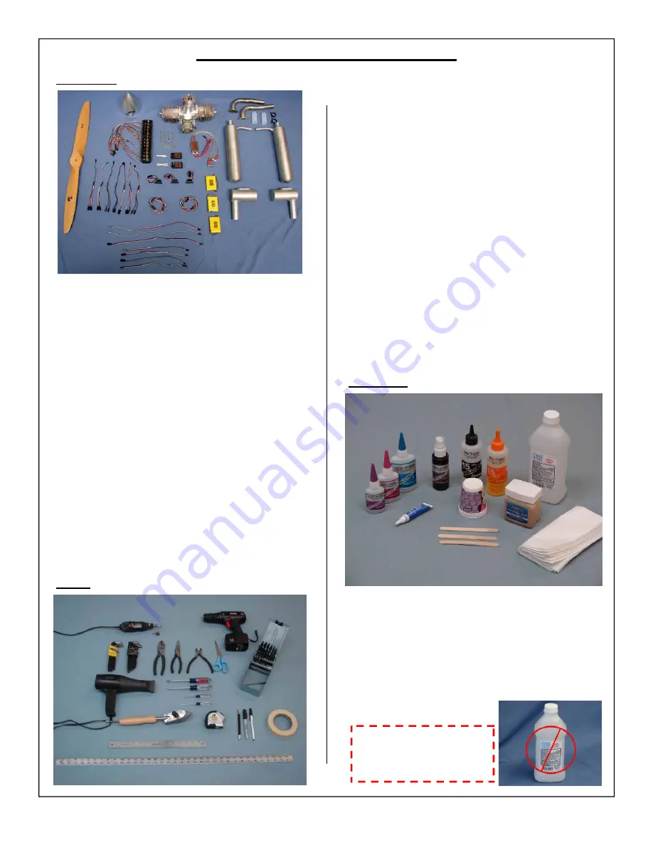
Adhesives:
•
15-30 Minute epoxy
•
Blue Loctite
(Thread Locker)
•
Epoxy mixing cups, sticks, brushes
•
CA kicker (optional)
•
Thick and Thin CA
•
Rubbing alcohol
•
Wipes
!WARRING!
Some rubbing alcohols
may attack painted parts.


