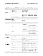
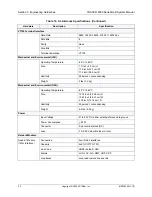
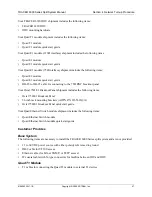
background image

Section 4  Network Turnup Procedure

TRACER 6000 Series Split System Manual

 46

Copyright © 2005 ADTRAN, Inc.

612806320L1-1B

1.

INTRODUCTION

This section discusses TRACER 6000 Series split system installation.

2.

TOOLS REQUIRED

The tools required for TRACER 6000 Series split system installation are:

VT100 terminal or PC with terminal emulation software

RS-232 (DB-9 male for TRACER 6200) cable for connecting to terminal

3.

UNPACK AND INSPECT THE SYSTEM

Each TRACER 6000 Series split system is shipped in its own cardboard shipping carton. Open each carton 
carefully and avoid deep penetration into the carton with sharp objects. 

After unpacking the unit, inspect it for possible shipping damage. If the equipment has been damaged in 
transit, immediately file a claim with the carrier; then contact ADTRAN Customer Service (see 

Warranty, 

Customer Service, Product Support Information, and Training

 information in the front of this manual).

Contents of Shipment

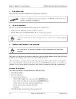
Your TRACER 6200 IDU shipment includes the following items:

TRACER 6200 IDU

Rackmount brackets

Accessory bag that includes:

RJ-45 to DB-9 adapter (for connection to the 

AUX RS232

 port)

6-foot silver satin cable (for connection to the 

AUX RS232

 port)

Alarm contact connector (3-position terminal block)

Power connector (2-position terminal block)

Extra fuse

TRACER 6000 Series Split System Documentation CD

Changes or modifications not expressly approved by ADTRAN could void the user’s 
authority to operate the equipment.

To prevent electrical shock, do not install equipment in a wet location or during a lightning 
storm.

This system MUST be installed by qualified service personnel in a Restricted Access 
Location.

Summary of Contents for TRACER 6000 SERIES

Page 1: ...1B June 2005 TRACER 6000 SERIES Split System Manual 12806200L1 TRACER 6200 Modular Indoor Unit IDU 12806320L1A TRACER 6320 5 8 GHz Outdoor Unit ODU Plan A 12806320L1B TRACER 6320 5 8 GHz Outdoor Unit...

Page 2: ...mages or for commercial losses even if ADTRAN has been advised thereof as a result of issue of this publication About this Manual This manual provides a complete description of the TRACER 6000 Series...

Page 3: ...f Changes A March 2005 Initial release of manual B June 2005 Added new real time power reportings and support for new Quad E1 120 module Notes provide additional useful information Cautions signify in...

Page 4: ...tub wash bowl kitchen sink laundry tub in a wet basement or near a swimming pool 2 Avoid using a telephone other than a cordless type during an electrical storm There is a remote risk of shock from li...

Page 5: ...uses and can radiate radio frequency energy If not installed and used in accordance with the instructions it may cause interference to radio communications The limits are designed to provide reasonab...

Page 6: ...f the antenna at a distance less than 15 feet 4 6 meters Installation on towers masts or rooftops not accessible to the general population is recommended or Mount the antenna in a manner that prevents...

Page 7: ...to obtain information regarding equipment currently in house or possible fees associated with repair Identify the RMA number clearly on the package below address and return to the following address Pr...

Page 8: ...program offers multiple types and levels of maintenance services which allow you to choose the kind of assistance you need This support is available at For questions call the ACES Help Desk Training T...

Page 9: ...rovides detailed descriptions of all menu options and configuration parameters available for the TRACER 6000 Series split system Section 6 Detail Level Procedures 89 Provides detailed instructions on...

Page 10: ...Table of Contents TRACER 6000 Series Split System Manual 10 Copyright 2005 ADTRAN Inc 612806320L1 1B...

Page 11: ...RACER 6000 Series split system CONTENTS System Overview 12 Features and Benefits 12 Configuration and Management 12 Operational 13 Available Interface Modules 13 E1 Network Module with 120 Interface 1...

Page 12: ...s provided for radio functionality Triple DES 3DES security provides additional protection from unauthorized access without requiring any additional external security appliances Future upgrades and en...

Page 13: ...rm reporting capability Testing support through local and remote line and link loopbacks E1 Network Module with 75 Interface Four E1 circuits provided through a single DB 25 75 connector Complies with...

Page 14: ...Section 1 System Description TRACER 6000 Series Split System Manual 14 Copyright 2005 ADTRAN Inc 612806320L1 1B...

Page 15: ...RACER RSSI Test Points 23 Antenna Beam Patterns 23 Fresnel Zones Earth Curvature and Antenna Heights 23 Other Considerations 26 Path Availability 26 FIGURES Figure 1 Example Microwave Path with Parame...

Page 16: ...ed signal power is often expressed in decibel format In general any quantity can be expressed in decibels If the quantity x is a power level in Watts the decibel equivalent is defined as If the quanti...

Page 17: ...omponents 4 RECEIVER POWER The viability of a particular microwave path is determined by the power of the transmitted microwave signal the transmit and receive antenna gain distance and accumulated sy...

Page 18: ...eristics of the antennas installed for each link In other words the size of the dish determines the antenna gain Using a parabolic dish antenna results in the best performance Antenna gains are specif...

Page 19: ...antennas For the TRACER 6320 these distances can range up to 30 miles 48 27 meters System Losses L System losses are defined by RF coaxial cable loss connector losses and losses added from any additi...

Page 20: ...s where f carrier frequency Hz carrier wavelength c f meters d path distance meters c speed of light free space meters In areas where lightning strikes are frequent a lightning arrestor should be inst...

Page 21: ...quency microwave communication experiences more path loss than lower frequency microwave communication The path loss values for various path lengths for the TRACER 5 8 GHz system are listed in Table 4...

Page 22: ...t required the delivered bandwidth can be decreased to four or two channels and the receiver sensitivity will be improved as follows 6 ANTENNA INFORMATION The overall wireless system is directly affec...

Page 23: ...nd RSSI voltage This sheet is useful for verifying link budget calculations and ensuring proper equipment installation Antenna Beam Patterns Directly related to the subject of antenna alignment is the...

Page 24: ...The curvature of the Earth becomes a legitimate obstruction for path lengths of 7 miles 11 26 kilometers or greater and must also be accounted for when determining minimum antenna heights The aggrega...

Page 25: ...gineering Basics 612806320L1 1B Copyright 2005 ADTRAN Inc 25 Table 8 Minimum Antenna Height for Given Path Lengths Metric Path Length kilometers Min Antenna Height meters 2 5 4 8 6 10 8 11 10 13 14 16...

Page 26: ...rier frequency GHz d path length kilometers F fade margin dB Terrain Factor a The terrain factor is a quantity that compensates the link availability for different types of terrain Generally speaking...

Page 27: ...ral microwave links operating in areas with high humidity will have less availability than those in arid areas primarily because water is a dispersive mechanism to microwave energy and causes the main...

Page 28: ...Section 2 Microwave Path Engineering Basics TRACER 6000 Series Split System Manual 28 Copyright 2005 ADTRAN Inc 612806320L1 1B...

Page 29: ...larm Contacts Plug In Terminal Block 35 To ODU Interface N Type Connector 36 TRACER 6320 Outdoor Unit ODU 36 RSSI Monitoring Interface 37 To IDU 37 Network Module Interfaces 37 4xE1 Module with 120 In...

Page 30: ...ntact Connector Pinout 35 Table 10 ODU Bottom Panel Description 36 Table 11 4xE1 Module with 120 Interface RJ 45 Connector Pinout 37 Table 12 4xE1 Module DB 25 Connector Pinout 38 Table 13 DB 25 to 75...

Page 31: ...anagement and configuration an AUX RS232 interface RJ 45 that provides an end to end serial port interface at 9600 bps and status LEDs to provide visual information about the TRACER system Figure 1 id...

Page 32: ...nt to point connection between the local and remote systems over the RF link Table 3 on page 33 shows the pinout Table 2 TRACER 6200 LEDs For these LEDs This color light Indicates that PWR Green solid...

Page 33: ...al ground 2 RTS Attached Equipment Request to send unused 3 TXDATA Attached Equipment Transmit data from attached equipment 4 DSR TRACER Data set ready 5 RXDATA TRACER Received data to attached equipm...

Page 34: ...Detailed discussions including pinouts of rear panel components where applicable follow the table Name Connector Description A Network Module Slots N A Dual network module slots for system flexibility...

Page 35: ...oximately 0 52 A 25 W 48 V Table 8 shows the DC power connection pinout Fuse The fuse holder accessible from the rear panel of the TRACER 6200 accepts a generic 2 A 250 V 2 inch slow blo fuse Alarm Co...

Page 36: ...the IDU The power supply is protected from a short circuit on the IDU ODU connection via a thermal protection device 5 TRACER 6320 OUTDOOR UNIT ODU Figure 3 identifies the features of the TRACER 6320...

Page 37: ...ection also provides a full duplex control and monitoring channel between the IDU and ODU on a 4 5 MHz carrier Additionally this interface accepts DC power from the IDU taken directly from the voltage...

Page 38: ...r the 4xE1 network module A separate breakout panel is available to provide 75 BNC unbalanced interfaces see Table 13 on page 39 for the pinout of the 75 cable Figure 4 displays the E1 breakout panel...

Page 39: ...me ESF and Super Frame SF framing support Manual line build out Network performance monitoring and reporting Test loopbacks both line and link Table 14 on page 40 provides the RJ 45 interface pinout f...

Page 40: ...ut for the Quad Ethernet Switch module 7 AT A GLANCE SPECIFICATIONS Table 16 on page 41 contains a list of specifications for the TRACER 6000 Series split system Table 14 4xT1 Module RJ 45 Connector P...

Page 41: ...uency Plan Plan A Band Plan 1 Tx 5 744 GHz Rx 5 824 GHz 2 Tx 5 747 GHz Rx 5 827 GHz 3 Tx 5 751 GHz Rx 5 831 GHz Plan B Band Plan 1 Tx 5 824 GHz Rx 5 744 GHz 2 Tx 5 827 GHz Rx 5 747 GHz 3 Tx 5 831 GHz...

Page 42: ...nical and Environmental ODU Operating Temperature 40 C to 65 C Size 12 74 inch 32 36 cm H 10 24 inch 26 01 cm W 4 78 inch 12 14 cm D Humidity 95 percent noncondensing Weight 9 5 lbs 4 3 kg Power Input...

Page 43: ...Loopbacks Local and remote line and link Quad T1 Module Connection Four RJ 45 interfaces Capacity 4xT1 ANSI T1 403 AT T 54016 and 62411 Line Code B8ZS default AMI Alarms AIS Red Yellow BPVs LOS Quad E...

Page 44: ...Section 3 Engineering Guidelines TRACER 6000 Series Split System Manual 44 Copyright 2005 ADTRAN Inc 612806320L1 1B...

Page 45: ...49 Mounting Options 50 Indoor Unit IDU 50 Outdoor Unit ODU 51 Installing Modules 52 Instructions for Installing Network Modules 53 Connecting the MODULE Interfaces 53 Quad T1 Module Interfaces 53 Qua...

Page 46: ...ansit immediately file a claim with the carrier then contact ADTRAN Customer Service see Warranty Customer Service Product Support Information and Training information in the front of this manual Cont...

Page 47: ...to the 75 BNC breakout panel Your Octal 75 E1 Breakout Panel shipment includes the following items Octal 75 E1 Breakout Panel 23 inch rack mounting brackets ADTN P N 3265622 A Octal 75 E1 Breakout Pa...

Page 48: ...at one end of the link will transmit in band plan 1 of frequency plan A the lower portion of the spectrum and receive in band plan 1 of frequency plan B the upper portion Consequently the receiver at...

Page 49: ...ary equipment grounding conductor shall be in compliance with the rules for terminating bonding jumpers at Part K or Article 250 of the National Electrical Code ANSI NFPA 70 Termination of the supplem...

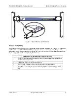
Page 50: ...Figure 3 on page 51 equipment racks using the supplied rackmount brackets 3265498 B Follow these steps to mount the TRACER 6200 into a rack Figure 2 19 inch Rackmount Illustration Instructions for Rac...

Page 51: ...outdoors using the provided mounting hardware Follow these steps to mount the TRACER 6320 ODU onto an outdoor structure see Figure 4 on page 52 for the accompanying illustration Instructions for Moun...

Page 52: ...ation as viewed from the rear of the TRACER 6200 IDU The functionally identical option slots only accept TRACER 6000 Series modules Figure 5 TRACER 6200 Network Module Slot Designation Access modules...

Page 53: ...can be damaged by static electrical discharge Before handling modules put on an antistatic discharge wrist strap to prevent damage to electronic components Place modules in antistatic packing materia...

Page 54: ...e s DB 25 connector and then attach the other end of the cable labeled TO PANEL to the BNC breakout panel The 75 unbalanced interfaces provided by the breakout panel are available for connection to st...

Page 55: ...U Error History 66 RF Link Max Min Received Power History 67 RF Link Min Max Received Signal Quality History 68 Datapath Provisioning 69 4xE1 Module Configuration Status History Main Screen 70 E1x Sta...

Page 56: ...Status History Main Screen 74 Figure 20 T1x Status Configuration Loopback 74 Figure 21 T1 Local Link Loopback 76 Figure 22 T1 Remote Link Loopback 76 Figure 23 T1 Local Line Loopback 76 Figure 24 T1...

Page 57: ...erial interface should be configured to NONE for proper operation Once a terminal is connected press Enter until the login screen appears The default password for the TRACER is password Terminal Menu...

Page 58: ...initial connection Enter twice Refresh the screen Ctrl l Ctrl r Exit the menu system and return to the login screen Ctrl z Close the Telnet session or toggle the modem signalling to hang up an attache...

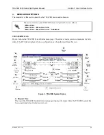
Page 59: ...igure 2 TRACER System Status A Elapsed Time The top of the TRACER System Status menu page displays the elapsed time the TRACER system has been operational since the last power reset The menu structure...

Page 60: ...oise ratio and features a colon marker to indicate 10 6 bit error rate This indicator is useful as a diagnostic tool to help 4XT1 MODULE A visual status of current errors alarms on the T1 interfaces f...

Page 61: ...ts using a series of symbols and the actual real time value in dBm The more symbols displayed the stronger the signal If the link is down in either direction and remote end data is unavailable DATA NO...

Page 62: ...FIGURATION SITE NAME Provides a user defined alphanumeric description up to 25 characters for the TRACER system SYSTEM CONFIGURATION SERIAL NUMBER Displays the serial number for the unit The serial nu...

Page 63: ...system Select one of the following 5 MIN 10 MIN default 15 MIN 30 MIN 45 MIN 60 MIN or OFF SYSTEM CONFIGURATION PASSWORD Sets the password for password protection of the TRACER terminal interface Ente...

Page 64: ...atures If the link is down in either direction and remote end data is unavailable DATA NOT AVAILABLE displays in place of the symbols This parameter is display only RF LINK CONFIGURATION TX POWER Allo...

Page 65: ...N is set to ENABLED the system sequentially applies the three keys entered in the SUBKEY 0 1 and 2 fields to each 64 bit block of data transmitted over the RF link The remote system uses the same keys...

Page 66: ...ys the error statistics available from the system for the RF link and the communications link between the IDU and ODU Detailed error statistics are displayed in 15 minute and 24 hour increments Figure...

Page 67: ...received power level MIN and MAX represents the minimum and maximum values of received signal levels in 24 hour or 15 minute increments and is displayed as a numerical value in dBm Press n to view the...

Page 68: ...uality Press n to view the next 8 hour segment of 15 minute totals and p to view the previous 8 hour segment Radio links with consistently high MIN and MAX numbers should not experience interference R...

Page 69: ...ION Defines the active channels A B C D on each installed T1 module or the bandwidth dedicated to the Quad Ethernet Switch module in 2 Mbps steps To activate a channel press Enter and use the spacebar...

Page 70: ...12 E1 Module Configuration Status History Main Screen E1X STATUS CONFIGURATION LOOPBACK Figure 13 shows the E1x Status Configuration Loopback menu page which displays a real time graphical representa...

Page 71: ...the E1 signal is properly timed Configure the framing format using the SIGNALING menu to enable the TRACER to monitor incoming framing error events and indicate problems with the attached metallic ser...

Page 72: ...LINK REMOTE Activates a loopback at the remote TRACER E1 framer towards the local end of the wireless link see Figure 15 Use the remote LINK loopback to loop the data transmitted from the local end of...

Page 73: ...Seconds SES on the E1 interface The following events qualify as an ES LOS OOF LCV or CRC error An SES is caused by a loss of signal or an out of frame event The error count for the most recent 24 hou...

Page 74: ...19 T1 Module Configuration Status History Main Screen T1X STATUS CONFIGURATION LOOPBACK Figure 20 shows the T1x Status Configuration Loopback menu page which displays a real time graphical representa...

Page 75: ...SIGNALING menu to enable the TRACER to monitor incoming framing error events and indicate problems with the attached metallic service The TRACER supports both extended superframe ESF and superframe D4...

Page 76: ...opback to loop the data transmitted from the local end of the link across the radio link to the local end of the link This loopback tests the integrity of the radio link and all the associated digital...

Page 77: ...ES AIS LOS or LOF alarm second a single BPV excessive zero event or a single parity bit An SES is caused by an AIS LOS or LOF alarm second excessive BPVs or framed parity bit errors causing a line bi...

Page 78: ...history parameters for the selected Ethernet Switch module Figure 26 Ethernet Switch Module Configuration Status History Main Screen ETHERNET SWITCH CONFIGURATION Figure 27 shows the Ethernet Switch...

Page 79: ...the system can be displayed on the Ethernet Switch Status page ETHERNET SWITCH STATUS Figure 28 shows the Ethernet Switch Status menu page which displays the current speed and duplex operation for ea...

Page 80: ...an indicator of congestion inside the TRACER switch ETHERNET SWITCH STATUS RX PACKET ERRORS Displays a counter of all received data packets that are greater than or equal to 64 bytes in length and ha...

Page 81: ...address is in dotted decimal notation four decimal numbers each in the range of 0 to 255 separated by periods This value is set to 255 255 255 0 by default This part of the destination IP address is...

Page 82: ...tch the Get or Set name defined on the NMS The default name is private MANAGEMENT SNMP PORT CONFIGURATION SNMP TRAP COMMUNITY Defines the community name for trap destinations This name must match the...

Page 83: ...t START or stop ABORT a ping request reset the ping statistics RESET STATS or return the ping configuration parameters to their default values DEFAULT VALUES PING UTILITY DELAY Read Only Displays the...

Page 84: ...WARE UPGRADE UTILITY TFTP FILENAME Available for TFTP transfers only Specifies the name of the update file to retrieve from the TFTP server Enter the full filename for the file Some TFTP servers requi...

Page 85: ...error message displays Refer to DLP 5 Updating the Firmware Using TFTP on page 101 for more details on available error messages FIRMWARE UPGRADE UTILITY REMOTE CURRENT STATUS Available for TFTP updat...

Page 86: ...o operate in a daisy chain fashions providing the user with configuration management and monitoring function for all TRACER systems in the chain as well as any other Ethernet capable device located on...

Page 87: ...the bridge table A shorter time produces a more dynamic bridge table allowing addresses to change network segments without causing extra forwarded traffic A longer time reduces the amount of unnecess...

Page 88: ...Section 5 User Interface Guide TRACER 6000 Series Split System Manual 88 612806320L1 1B...

Page 89: ...e system and upgrading firmware CONTENTS DLP 1 Connecting a VT100 Terminal or PC to the CRAFT Port 91 DLP 2 Logging into the TRACER System 93 DLP 3 Setting IP Parameters for the TRACER System 95 DLP 4...

Page 90: ...Section 6 Detail Level Procedures TRACER 6000 Series Split System Manual 90 612806320L1 1B...

Page 91: ...R Prerequisite Procedures The TRACER must be powered up for terminal communication to function Tools and Materials Required A VT100 compatible terminal or PC with terminal emulation software An approp...

Page 92: ...rm one of the following steps Set the parameters of the VT100 terminal or PC to 9600 baud rate 8 data bits No parity 1 stop bit No flow control If the terminal has a parallel setting disable this sett...

Page 93: ...C to the CRAFT Port on page 91 To prevent electrical shock do not install equipment in a wet location or during a lightning storm Electronic equipment can be damaged by static electrical discharge Bef...

Page 94: ...cursor at the LOGIN field indicates that a password must be entered 2 Enter the password for the TRACER at the LOGIN field The manufacturer s default password for the TRACER system is password in lowe...

Page 95: ...s connected to an IP network and is powered up Please see your Network Administrator for the proper assignment of the following parameters IP ADDRESS SUBNET MASK and DEFAULT GATEWAY To prevent electri...

Page 96: ...ximum rights details are in DLP 2 Logging into the TRACER System on page 93 2 Press m to activate the Main menu page From the Main menu page press 7 to select MANAGEMENT UTILITIES 3 From the MANAGEMEN...

Page 97: ...nu page select the IP ADDRESS field and press Enter Type the IP address provided by your network manager and press Enter to accept the change Repeat the process for the SUBNET MASK and DEFAULT GATEWAY...

Page 98: ...Section 5 DLP 3 TRACER 6000 Series Split System Manual 98 Copyright 2005 ADTRAN Inc 612806320L1 1B...

Page 99: ...provisioning tasks detailed in DLP 3 Setting IP Parameters for the TRACER System on page 95 should be complete Tools and Materials Required Access to a PC or other computer connected to the LAN To pr...

Page 100: ...45 connector Verify the IP address subnet mask and default gateway on the remote computer system If these steps fail contact the LAN Administrator for assistance 3 Telnet to the TRACER From the same c...

Page 101: ...ort and a TFTP server See DLP 6 Updating the Firmware Using XMODEM on page 105 for instructions on using XMODEM Tools and Materials Required A PC with Telnet client software A TFTP server accessible o...

Page 102: ...TFTP provides the capability to upgrade both sections of the local and remote units Valid choices are LOCAL IDU LOCAL ODU REMOTE IDU and REMOTE ODU 9 View CURRENT UPDATE STATUS to verify the progress...

Page 103: ...Service channel communications over the RF link allow a user connected to a local system to upgrade the firmware of a remote system Before the remote system begins the firmware upgrade process a compl...

Page 104: ...th the ODU to obtain the current firmware revision of the system This only occurs when the local or remote ODU is selected from the UPGRADE DESTINATION field REQUIRED COMMUNICATIONS LINK IS DOWN Indic...

Page 105: ...ugh your Telnet client refer to your Telnet client documentation for more details on file transfer specifics See DLP 5 Updating the Firmware Using TFTP on page 101 for instructions on using TFTP Tools...

Page 106: ...for possible configuration errors 10 From the terminal emulation software begin the XMODEM upload by using the appropriate command sequence This may take several minutes If necessary refer to the term...

Page 107: ...CER 6000 split system 108 MIB Compilation Order 108 Traps Supported by the TRACER 6000 split system 109 MIB Variables Supported by the TRACER 6000 split system 111 TABLES Table 1 MIBs Supported by the...

Page 108: ...types rfc2863 mib IF MIB updated MIB II rfc3418 mib SNMPv2 MIB rfc3595 mib PerfHist TC MIB needed for RFC2495 rfc3635 mib EtherLike MIB adtran mib ADTRAN product MIB needed to locate the ADTRAN specif...

Page 109: ...change in the Code Violation CV state has occurred and the CV alarm is active adTRACERCRC a change in the Cyclic Redundancy Check CRC state has occurred and the CRC alarm is active adTRACERmfLOF a cha...

Page 110: ...Remote Alarm RA has occurred and the Multiframe RA alarm is inactive adTRACERlineLoopbackOff a change in the line loopback state has occurred and the line loopback is inactive adTRACERlinkLoopbackOff...

Page 111: ...adProdName DisplayString RO adProdPartNumber DisplayString RO adProdCLEIcode DisplayString RO adProdSerialNumber DisplayString RO adProdRevision DisplayString RO adProdSwVersion DisplayString RO adPro...

Page 112: ...rm Integer RW adDS1TotalArm Integer RW adDS1FarCurrentArm Integer RW adDS1FarTotalArm Integer RW adDS1CurrentThreshold adDS1CurrentThrsES Integer RW adDS1CurrentThrsSES Integer RW adDS1CurrentThrsSEFS...

Page 113: ...CERactiveChannels Integer RW adTRACERchannelSelect adTRACERdsx1ChannelSelectTable adTRACERdsx1ChannelSelectEntry AdTRACERdsx1ChannelSelectEntry adTRACERdsx1ChannelSelectIdx Integer RO adTRACERdsx1Chan...

Page 114: ...CERswitchWanStatusEntry AdTRACERswitchWanStatusEntry adTRACERswitchWanStatusIdx Integer RO adTRACERswitchWanTxPackets Integer RO adTRACERswitchWanTxPacketsDrop Integer RO adTRACERswitchWanRxPackets In...

Page 115: ...s Integer RO adTRACERIntervalMaxRxLs Integer RO adTRACERIntervalMinRxLs Integer RO adTRACERIntervalMaxRxQs Integer RO adTRACERIntervalMinRxQs Integer RO adTRACERIntervalValidData TruthValue RO adTRACE...

Page 116: ...chChannelSelectTable AdTRACERremoteSwitchChannelSelectEntry adTRACERremoteSwitchChannelSelectEntry adTRACERremoteSwitchChannelSelectIdx Integer RO adTRACERremoteSwitchChannelSelection Integer RW adTRA...

Page 117: ...etsDrop Integer RO adTRACERremoteswitchWanRxPacketError Integer RO adTRACER6420remoteTrapIP adTRACERremoteTrapIpHost1 IpAddress RW adTRACERremoteTrapIpHost2 IpAddress RW adTRACERremoteTrapIpHost3 IpAd...

Page 118: ...eIntervalMaxRxQs Integer RO adTRACERremoteIntervalMinRxQs Integer RO adTRACERremoteIntervalValidData TruthValue RO adTRACERremoteTotalTable AdTRACERremoteTotalEntry adTRACERremoteTotalEntry adTRACERre...

Page 119: ...NTENTS Overview 120 LED Indicators 120 PWR LED 120 TST LED 120 RF DWN LED 120 RF LOW LED 121 T1 Interface Alarms 121 E1 Interface Alarms 122 LAN LEDs 123 RF Errors 123 Step by Step Troubleshooting 124...

Page 120: ...ort on the IDU 5 Verify the integrity of the coaxial feedline cable between the IDU and ODU 6 Verify the integrity of the lightning arrestors both RF and IF TST LED The TST LED will flash once amber d...

Page 121: ...herproof the replacements 3 Verify the RF signal path by verifying the antenna alignment 4 Check the integrity of lightning arrestors T1 Interface Alarms All active T1 alarms are displayed in the T1X...

Page 122: ...Actions 1 Display the E1 X STATUS screen and check the E1 X INTERFACE ALARM field to identify the active alarm 2 Follow the steps below for the appropriate alarm LOS Alarm Loss of Signal LOS ALARM is...

Page 123: ...nd in band RF interference These types of errors are remedied by performing a detailed line of site microwave path study to determine whether a microwave link is feasible for the terrain and environme...

Page 124: ...mately 100 mW 20 dBm of RF power The actual power level measured by the meter analyzer will be less than 100 mW due to RF losses through the coaxial cable and is a function of the cable type and lengt...

Page 125: ...equipment This will verify the data path across the RF link Installing Configuring T1 Hardware 1 If possible attach any or all of the intended T1 hardware to the TRACER units using the same workbench...

Page 126: ...ion resolve any remaining E1 equipment to TRACER configuration issues before field installation See E1 Interface Alarms on page 122 for more information on resolving E1 interface alarm conditions Inst...

Reviews: