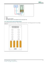
9.4.1 Layout of the Printed Circuit Board (PCB)
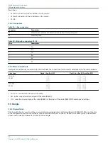
9.4.2 Straps
Table 42: Multiwire PCB straps
Strap
Description
W5
Internal voltage for remote control.
W6
Internal voltage for back indication signals.
9.4.3 Connectors
Table 43: Multiwire PCB connectors
Connector
Connection to
P1
Back-indication/output signals
The connector type is WAGO 231-312/026-000 cage-clamp connector. This connector can accept wires
of 0.08 to 2.5 mm2 (28 - 12 AWG).
P2
Control/input signals
The connector type is WAGO 231-312/026-000 cage-clamp connector. This connector can accept wires
of 0.08 to 2.5 mm2 (28 - 12 AWG).
P3
Flat cable connection to the LMC.
J1
Power supply to the multiwire interface PCB
Flashing System Maintenance
PCB drawings and settings
84
Copyright
©
ADB Safegate, All Rights Reserved
Summary of Contents for FCU-1-in-1
Page 2: ......
Page 8: ...Flashing System Maintenance TABLE OF CONTENTS viii Copyright ADB Safegate All Rights Reserved ...
Page 18: ...Flashing System Maintenance Safety 8 Copyright ADB Safegate All Rights Reserved ...
Page 28: ...Flashing System Maintenance Introduction 18 Copyright ADB Safegate All Rights Reserved ...
Page 42: ...Flashing System Maintenance Commissioning 32 Copyright ADB Safegate All Rights Reserved ...
Page 64: ...Flashing System Maintenance Maintenance 54 Copyright ADB Safegate All Rights Reserved ...
Page 106: ...Flashing System Maintenance Technical data 96 Copyright ADB Safegate All Rights Reserved ...
Page 110: ......


