background image

You can modify the settings at any time with the configuration software tool.

Table 49: Default back-indication signals

P1

Signal

Function

1

Output 1

SFL running - contact closed when running

2

Output 2

RTILS/REILS running - contact closed when running

3

Output 3

REILS DOWN - contact closed in case of alarm

4

Output 4

Misfire on 1 FCU (latched) - contact closed in case of an alarm

5

Output 5

Misfire on 2 consecutive FCUs (latched) - contact closed in case of an alarm

6

Output 6

Communication error on local bus + Security (Door + MOV) – contact open in case of an

alarm

7

Output 7

Over temperature – contact closed in case of an alarm

8

Output 8

Custom 1

9

Common

Common output signals

10

GNDext

Earthing multiwire PCB

11

Vext+

Power supply from multiwire PCB (24 V or 48 V)

12

PE

Earth connection

Remote control signals
You can modify the settings with the configuration software tool.

Table 50: Default remote control signals

P1

Signal

Function

1

Input 1

SFL ON Step 1

2

Input 2

SFL ON Step 2

3

Input 3

SFL ON Step 3

4

Input 4

REILS/RTILS ON step 1

5

Input 5

REILS/RTILS ON step 2

6

Input 6

REILS/RTILS ON step 3

7

Input 7

Reset alarms

8

Input 8

Free

9

Common

Common input signals

10

GNDext

GND multiwire PCB

11

Vext+

Power supply from multiwire PCB (24 V or 48 V)

12

PE

Earth connection

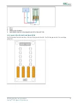
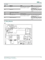
9.5 J-Bus Connection - PCB1502

The PCB provides the connection between the user J-Bus(ses) and the LMC.
The J-Bus interface uses a single or dual databus(es) to allow remote monitoring of a bigger quantity of parameters.
An equipment is always a slave on the J-Bus. There can be a maximum of 31 equipments on one bus section with one

common bus master.

Flashing System Maintenance
PCB drawings and settings

88
Copyright 

©

 ADB Safegate, All Rights Reserved

Summary of Contents for FCU-1-in-1

Page 1: ...Flashing System Maintenance Types FCU 3 in 1 and FCU 1 in 1 User Manual UM 4019_AM02 620e Rev 3 0 2020 05 12 ...

Page 2: ......

Page 3: ...require such new parts to be furnished ADB SAFEGATE s liability under no circumstances will exceed the contract price of goods claimed to be defective Any returns under this guarantee are to be on a transportation charges prepaid basis For products not manufactured by but sold by ADB SAFEGATE warranty is limited to that extended by the original manufacturer This is ADB SAFEGATE s sole guarantee an...

Page 4: ... or incompatible with your ADB SAFEGATE equipment Allowing unskilled personnel to perform any task on or with the equipment ADB SAFEGATE BV This manual or parts thereof may not be reproduced stored in a retrieval system or transmitted in any form or by any means electronic mechanical photocopying recording nor otherwise without ADB SAFEGATE BV s prior written consent This manual could contain tech...

Page 5: ... Main commissioning procedure 19 4 2 Configure the FCU PCBs 19 4 2 1 Set the communication parameters 19 4 2 2 Define the equipment address 19 4 3 Configure the flashing system 21 4 3 1 General procedure 21 4 3 2 Manual configuration 21 4 3 3 Configuration with the configuration software tool 22 4 4 Remote control configuration multiwire option 27 4 5 Remote control configuration J Bus option 28 4...

Page 6: ...65 8 1 Install configuration software tool on a PC 65 8 1 1 Requirements 65 8 1 2 Install software 65 8 2 Start configuration software tool 65 8 2 1 Connect cables 65 8 2 2 Start software 66 8 3 Upload new firmware 66 8 4 Description of screens and menus 69 8 4 1 Configuration software tool screen 69 8 4 2 Control menu 70 8 4 3 Mode menu 70 8 4 4 Flasher data menu 70 8 4 5 IO menu 73 8 4 6 Timing ...

Page 7: ...90 9 5 3 Slave connections 90 9 6 Dongle 90 9 6 1 Dip switches 90 9 6 2 LEDs 91 9 7 Wiring diagrams 91 10 0 Technical data 93 10 1 Technical characteristics 93 10 2 Ambient conditions 93 10 3 Parts list 93 10 3 1 General 93 10 3 2 General parts 94 10 3 3 LMC and remote control parts 95 10 3 4 Optional parts 95 A 0 SUPPORT 97 A 1 ADB SAFEGATE Website 97 A 2 Recycling 97 A 2 1 Local Authority Recycl...

Page 8: ...Flashing System Maintenance TABLE OF CONTENTS viii Copyright ADB Safegate All Rights Reserved ...

Page 9: ...Mode menu 70 Table 16 Status menu 70 Table 17 Active state menu 70 Table 18 Misfire state and counter menu 71 Table 19 Flasher counter menu 71 Table 20 Flasher temperature menu 71 Table 21 Flasher security menu 71 Table 22 Flasher steps menu 72 Table 23 Software version menu 72 Table 24 Read communication counters menu 72 Table 25 Read flasher counters menu 72 Table 26 IO menu 73 Table 27 Timing m...

Page 10: ...ion P2 wires per power supply type 85 Table 46 Functions for connector P1 86 Table 47 Connect P1 wires per power supply type 87 Table 48 Multiwire options 87 Table 49 Default back indication signals 88 Table 50 Default remote control signals 88 Table 51 J Bus connectors 90 Table 52 Wiring for connectors P1 P4 90 Table 53 Technical characteristics 93 Table 54 Ambient conditions 93 Flashing System M...

Page 11: ...rve this warning may result in personal injury death or equipment damage ARC Flash may cause blindness severe burns or death WARNING Wear personal protective equipment Failure to observe may result in serious injury WARNING Do not touch Failure to observe this warning may result in personal injury death or equipment damage CAUTION Failure to observe a caution may result in equipment damage Qualifi...

Page 12: ...h safety devices as specified by applicable safety regulations If safety devices must be removed for installation install them immediately after the work is completed and check them for proper functioning prior to returning power to the circuit Failure to follow this instruction can result in serious injury or equipment damage Additional Reference Materials Important Information IEC International ...

Page 13: ...se the light fixture will be installed in in order to chose the correct gasket bolts and nuts Bolt type length and torque value are determined by type of base height of spacers used and clamp force required in FAA Engineering Brief No 83 latest revision Due to the risk of bolts vibrating loose do not use any type of washer with the fixing bolts such as split lock washers other than an anti vibrati...

Page 14: ... Protect equipment with safety devices as specified by applicable safety regulations If safety devices must be removed for installation install them immediately after the work is completed and check them for proper functioning Route electrical wiring along a protected path Make sure they will not be damaged by moving equipment Never operate equipment with a known malfunction Do not attempt to oper...

Page 15: ...struments for intra beam viewing The Laser Scanning Unit compartment of the Pilot Display unit contains a Laser Range Finder which is a Class 1M laser product A Class 1M laser product is safe under foreseeable conditions of operation but may be hazardous if the user employs optical instruments within the beam e g binoculars or telescope Failure to follow this instruction can result in permanenet e...

Page 16: ...n permanenet eye injury Table 1 Laser Information For the laser the following values apply Pulse width 10 ns Wavelength 905 nm CAUTION If the laser by any reason should be switched on and used outside the docking system safety procedures may include but are not necessarily limited to the following Do not stare into the laser beam Do not view the beam with binoculars or other devices that collect l...

Page 17: ... who are properly trained and familiar with ADB SAFEGATE equipment are permitted to service this equipment An open airfield current circuit is capable of generating 5000 Vac and may appear OFF to a meter Never unplug a device from a constant current circuit while it is operating Arc flash may result Disconnect and lock out electrical power Always use safety devices when working on this equipment F...

Page 18: ...Flashing System Maintenance Safety 8 Copyright ADB Safegate All Rights Reserved ...

Page 19: ...onfiguration AWG American Wire Gauge Binary notation All data in the digital circuits is treated using 1 and 0 Thus all decimal notations are transcripted into binary notations CPU Central processing unit DC Direct Current E PROM Electronically Erasable Programmable Read Only Memory Equipment Both FCU 1 and FCU 3 if the information is the same FAA Federal Aviation Administration Fastener Generic t...

Page 20: ...ion bus which communicates with the customer control system MOV Metal Oxide Varistor MW Multiwire ODALS Omni Directional Approach Lighting System PC Personal Computer PCB Printed Circuit Board PCMCIA Personal Computer Memory Card International Association PE Protective Earth PU PolyUrethane RC circuit Circuit wit a resistance and a capacity REILS Runway End Identification Lighting System RTILS Run...

Page 21: ...ents of a flashing system The design plan shows the actual lay out A flashing system can contain up to 32 flashing heads Every flashing system has one LMC The LMC can be installed in an FCU 1 cabinet or in a FCU 3 cabinet UM 4019_AM02 620e Rev 3 0 2020 05 12 11 Copyright ADB Safegate All Rights Reserved ...

Page 22: ...3 2 Lay out of the equipment cabinets 3 2 1 FCU 1 Flashing System Maintenance Introduction 12 Copyright ADB Safegate All Rights Reserved ...

Page 23: ...3 2 2 FCU 3 UM 4019_AM02 620e Rev 3 0 2020 05 12 13 Copyright ADB Safegate All Rights Reserved ...

Page 24: ... for a single flash unit single phase power supply FCU 3 one cabinet with three FCUs for 3 flash units three phase power supply It is possible to combine these two types of cabinets in one system Then FCU 1 cabinets must have a separate junction box option to connect to the three phase power supply It is possible to connect the FCU 3 in a single phase power supply Then the number of flash units is...

Page 25: ...erconnects all the devices of a system as a part of an RS 485 protocol Inside the equipment cabinets the equipments are pre connected at delivery The interconnection of all equipment cabinets in a flashing system must be realized with a screened dual twisted pair connection The local bus connection board has a set of gas arresters that provide over voltage protection for the local bus wiring 3 5 L...

Page 26: ...The equipment can be supplied with an extra over voltage protection When an overvoltage is supplied to the individual equipment cabinets the over voltage protection activates An alarm can be generated through the feedback of the LMC When the origin of the problem is solved it is necessary to replace the MOV cartridge Dongle The dongle enables you to connect the equipment directly to a PC A special...

Page 27: ...are tool It is necessary to configure a specific signal only to one terminal Control signals The control signals feed relay coils An RC circuit protects the relay coils for transient over voltage Table 3 Multiwire options Multiwire 48 VDC remote control 24 VDC remote control Minimum voltage 40 VDC 21 6 VDC Maximum voltage 65 VDC 35 VDC Current consumption Approximately 9 mA at 48 VDC Approximately...

Page 28: ...Flashing System Maintenance Introduction 18 Copyright ADB Safegate All Rights Reserved ...

Page 29: ...he factory setting Note Do not change the setting as indicated in the illustration First contact ADB if you want change this setting 4 2 2 Define the equipment address Each FCU PCB in the system must have its own unique binary address Note If RTILS REILS are present Configure an unique address to both REILS or RTIL units Make sure the REILS or RTILS have the highest binary and physical address Phy...

Page 30: ... that is the furthest away from the runway Note First contact ADB if you want to change this logical order Example for a flashing system with both FCU 1 and FCU 3 units Note The example shows a non existing set of 10 flasher heads A normal flashing system contains 2 21 23 30 or 32 flasher heads The example only shows the logical order to number Equipment cabinet Dip switch SW2 set to A furthest aw...

Page 31: ...rning Make sure that all power to the FCU cabinet is OFF before you set the dip switches 1 Enable local control 2 Enable manual configuration 3 Set the number of equipments in the system 4 Set the sequence timing and RTILs REILs 5 Restart the LMC Use the fused input switch Enable local control 6 Set the rotary switch of the LMC PCB to 0 Enable manual configuration 7 Set the dip switch 4 of dip swi...

Page 32: ...he system are switched ON 12 Switch OFF the equipment that has the LMC Leave the power off for approximately 10 seconds 13 Switch ON the equipment that has the LMC Use the fused input switch Now the flashing system reads the dip switches and adapts to changes you made since the last power cycle on the equipment that has the LMC 4 3 3 Configuration with the configuration software tool General proce...

Page 33: ...dip switch bank SW5 of the LMC PCB Dip switches 1 to 6 set the same as for SW2 for the last flasher head in the flashing system See Define the equipment address Dip switch 8 ON Dip switch 8 allows the communication over the dongle to the LMC PCB Restart LMC 9 Make sure that the all equipment cabinets in the system are switched ON 10 Switch OFF the unit that has the LMC Leave the power off for appr...

Page 34: ...LS or REILs if applicable 16 Set the number of equipment cabinets boxes Set the flashing system layout 17 Set a flashing sequence and a slave number for each flasher head Preferably work in a logical order set the sequence number equal to the slave number and set the the first flasher head in the flashing system to 1 18 Set some of the flasher heads to be REILs or RTILs if applicable Click the fie...

Page 35: ...n Flasher data 22 Press Status 23 Check if the status of the LMC and all flasher heads is Online 24 If this is not the case check the power supply to all equipment cabinets The power supply to all equipment cabinets The position of the door switches The binary addresses on the FCU PCBs The local bus communication cables Define the flashing mode Set the flashing mode UM 4019_AM02 620e Rev 3 0 2020 ...

Page 36: ... These flashing modes are available ASLF 1 ASLF 2 SSALR SSALS MALSR MALSF ODALS Custom any of the above modes can be changed user defined Only if you need to change the standard setting of a mode 30 Check and change if necessary the cycle time for each mode 31 Define which flashers are included in the selected mode 32 Check if the correct number of flashers is active The box of an active flasher i...

Page 37: ...ntrol functions For the factory settings see J Bus Connection PCB1502 Change the input and output signals if applicable 4 In the configuration software tool open menu IO 5 Simulate an error 6 Check if the remote control receives the signals 7 To change the input and output signals of the multiwire boards click the terminal fields A pop up window appears See also Input terminals and Output terminal...

Page 38: ...itches of dip switch bank SW1 according to the databus connection of the equipment cabinet For details see Local Master Controller LMC PCB1513 4 5 3 Set slave address The slave on the databus must have a unique binary address Change the settings of the dip switches of dip switch bank SW1 on the LMC PCB 4 5 4 Set two four wire communication Set the straps on the LMC PCB See Local Master Controller ...

Page 39: ...the remote control receives the signals 4 6 Commissioning records 4 6 1 Use tables Use the tables to record all the necessary information in the commissioning phase 4 6 2 Commissioning record tables Table 5 Commissioning record tables general Approach Mode name Cycle time in seconds Table 6 Commissioning record tables flasher head 1 to 11 Flasher head 1 2 3 4 5 6 7 8 9 10 11 Equipment cabinet SW2 ...

Page 40: ...ord tables flasher head 23 to 32 Flasher head 23 24 25 26 27 28 29 30 31 32 Equipment cabinet SW2 address REIL RTIL FCU 3 FCU 1 FCU 1 phase connect Termination resistance set P1 P3 to P1 P3 to Timing ms Group 4 6 3 J bus settings table option Hardware present Bus A Bus B Arbiter Arbiter Local kill Local kill Default Breakdown mode Default mode Default step Default step REIL Flashing System Mainten...

Page 41: ...on 1 Output 1 2 Output 2 3 Output 3 4 Output 4 5 Output 5 6 Output 6 7 Output 7 8 Output 8 9 Common 10 GNDext 11 Vext 12 PE Remote control signals Table 10 Customized remote control signals P1 Signal Function 1 Input 1 2 Input 2 3 Input 3 4 Input 4 5 Input 5 6 Input 6 7 Input 7 8 Input 8 9 Common 10 GNDext 11 Vext 12 PE UM 4019_AM02 620e Rev 3 0 2020 05 12 31 Copyright ADB Safegate All Rights Rese...

Page 42: ...Flashing System Maintenance Commissioning 32 Copyright ADB Safegate All Rights Reserved ...

Page 43: ...ning Make sure you have read and understood all safety procedures and standards related to this equipment See Safety Warning Make sure you switch OFF the power supply See Prepare Switch OFF power supply CAUTION While you carry out maintenance make sure that You do not drop any screws or nuts inside the equipment cabinet Collect all loose nuts and screws immediately You can identify all cables you ...

Page 44: ...witch Local bus connection board See Local bus connection board Wiring assembly See Wiring assembly Cable entry kit with bottom See Cable entry kit with bottom Choke See Choke Mains filter See Mains filter Overvoltage protection MOV See Overvoltage protection cartridge MOV Covers See Remove covers 5 2 1 Required tools Multimeter Standard electrical and mechanical tool kit Screwdrivers with protect...

Page 45: ...PCB Remove base plate 1 Make sure that all power to the equipment is OFF See Prepare Switch OFF power supply 2 Remove the cover See Remove covers 3 Disconnect all the connectors on the PCB Use pliers for the connectors in TB3 if necessary 4 Loosen the fasteners A Use an angle socket wrench for the nuts 5 Remove the base plate B 6 Disconnect the cables from the two cable retainers C Remove PCB from...

Page 46: ...removed FCU PCB 14 Tighten the two screws B 15 Tighten the nine nuts A CAUTION Tighten the screws B before you tighten the nuts A to ensure the correct coupling of the cooling plate of the board with the base plate Install 2 16 Install the fasteners A and install the base plate B Use an angle socket wrench for the nuts Install 3 Flashing System Maintenance Maintenance 36 Copyright ADB Safegate All...

Page 47: ...Install the cover 19 Close the cabinet door 20 Check if the FCU PCB works correctly See Checks and measurements 5 2 4 FCU 1 PCB or FCU 3 middle PCB The procedure applies to the PCB of the FCU 1 and the middle PCB of the FCU 3 Remove 1 Make sure that all power to the equipment is OFF See Prepare Switch OFF power supply 2 Remove the cover See Remove covers 3 Disconnect all the connectors on the PCB ...

Page 48: ...e cables to the connectors Power supply to P6 If necessary to identify the connector measure for 230 V AC input supply to the AC DC supply connector on P7 Only for FCU 1 Heater connection to P5 MOV connection to P3 Power distribution from the DC unit to TB1 Door switch to P2 Capacitor terminal connection to TB3 red wire to 400 and blue white wire to PE Coil connection to TB4 RET and TRIG Flasher h...

Page 49: ... Prepare Switch OFF power supply Replace 6 Disconnect the cables to the LMC PCB 7 Remove the eight nuts A 8 Replace the LMC PCB B 9 Set the dip switches and straps to the same settings as the old LMC PCB 10 Install the eight nuts A Connect cables 11 Connect the cables to the connectors Power distribution from the DC unit to TB1 MOV connection to P6 Door switch to P7 External temperature probe to P...

Page 50: ...Switch OFF power supply Configure 19 Configure the flashing system See Configure the flashing system 5 2 6 Multiwire PCB The procedure applies to both 24 V DC and 48 V DC type of multiwire PCBs Replace 1 Make sure that all power to the equipment is OFF See Prepare Switch OFF power supply 2 Disconnect the cables from the multiwire PCB B 3 Remove the nuts A Use a number 5 5 socket wrench 4 Replace t...

Page 51: ...ure that all power to the equipment is OFF See Prepare Switch OFF power supply 2 Disconnect the flat multiwire cable A from the connector P5 of the LMV PCB and P3 of the multiwire PCB 3 Install the new multiwire cable A 4 Connect the multiwire cable A to the connector P5 of the LMC PCB and P3 of the multiwire PCB 5 Close the cabinet door 6 Check the remote control functions 7 Close the cabinet doo...

Page 52: ...e a number 5 5 socket wrench Connect 6 Connect the cables to the connectors LMC to P6 J Bus control for Bus A to P1 and P2 J Bus control for Bus B to P3 and P4 Earth wire to the ground terminal 7 Close the cabinet door 8 Check the remote control functions 9 Configure the flashing system See Configure the flashing system 10 Close the cabinet door 5 2 9 Capacitor Prepare 1 Make sure that all power t...

Page 53: ...bolt B Use a size 19 wrench 11 Install the cover 12 Close the cabinet door 5 2 10 DC power supply Prepare The DC power supply module receives its input power from the FCU PCB through the connector P7 In an FCU 3 cabinet one FCU PCB provides power to the DC power supply 1 Make sure that the FCU PCB and the fuses F1 F2 and F3 work correctly DC power supply module Remove 2 Make sure that all power to...

Page 54: ...et door DC power supply fuse 13 Make sure that all power to the equipment is OFF See Prepare Switch OFF power supply 14 Remove the DC power supply module See the procedure above 15 Remove the two screws A 16 Remove the cover B 17 Remove the fuse C The fuse has a clip on connection 18 Install the a new fuse C Make sure that the type is applicable for the module 19 Install the cover B 20 Install the...

Page 55: ...ires C to the two middle connectors of the door switch B 8 Install the two screws A 9 Close the cabinet door 5 2 12 Local bus connection board Remove 1 Make sure that all power to the equipment is OFF See Prepare Switch OFF power supply 2 Record how the local bus cables are connected to the connectors 3 Disconnect the connectors on the local bus connection board A 4 Disconnect the earth wire The e...

Page 56: ... cabinet door 5 2 13 Wiring assembly FCU 1 Disconnect 1 1 Make sure that all power to the equipment is OFF See Prepare Switch OFF power supply 2 Remove the cover See Remove covers 3 Disconnect the cables Power input terminals and protective earth terminals A FCU PCB connectors P7 P6 and P5 B DC power supply input wires C Multiwire PCB J1 D 4 Remove the cable binders from the disconnected cables Fl...

Page 57: ...r cut the two soldered connections F Replace 10 Remove the wiring assembly 11 Install the new wiring assembly Maintenance Connect 1 12 Connect the seven cables of the fuses F1 and F2 Connect heater cables 13 Slide thermo retractable insulation sleeves on the cables 14 Solder one cable on the connection point A on both sides of the heater UM 4019_AM02 620e Rev 3 0 2020 05 12 47 Copyright ADB Safega...

Page 58: ...ut wires E Multiwire PCB J1 F 21 Bind the cables Use cable binders 22 Close the cabinet door FCU 3 Disconnect 1 23 Make sure that all power to the equipment is OFF See Prepare Switch OFF power supply 24 Disconnect the cables Power input terminals L1 L2 and L3 and protective earth terminals A FCU 1 PCB connectors P7 P6 and P5 B FCU 2 PCB connectors P6 and P5 C FCU 3 PCB connector P5 D DC power supp...

Page 59: ...connect the cables Fuses F1 F2 and F3 Over voltage protection MOV if applicable Socket if applicable Three mains filters Heater cut the two soldered connections Replace 29 Remove the wiring assembly 30 Install the new wiring assembly Connect 1 UM 4019_AM02 620e Rev 3 0 2020 05 12 49 Copyright ADB Safegate All Rights Reserved ...

Page 60: ... over the solder points Connect 3 35 Install the rail A 36 Install the two screws B 37 Connect the cables Power input terminals L1 L2 and L3 and protective earth terminals A FCU 1 PCB connectors P7 P6 and P5 B FCU 2 PCB connectors P6 and P5 C FCU 3 PCB connector P5 D DC power supply input wires E Local bus connection board F Multiwire PCB J1 G 38 Bind the cables Use cable binders 39 Install the co...

Page 61: ...the new bottom plate C 6 Cut the glands of the bottom plate into an applicable size 7 Put the cables through the glands D 8 Connect the cables 9 Close the cabinet door 5 2 15 Choke The FCU 3 has three chokes The FCU 1one choke 1 Make sure that all power to the equipment is OFF See Prepare Switch OFF power supply 2 Remove the cover See Remove covers 3 Remove the four screws A 4 Disconnect the cable...

Page 62: ... PE N and P and the two output connectors N and P 4 Remove the two screws A 5 Remove the mains filter B 6 Install the new mains filter B 7 Install the two screws A 8 Connect the three input connectors PE N and P and the two output connectors N and P 9 Close the cabinet door 5 2 17 Overvoltage protection cartridge MOV 1 Make sure that all power to the equipment is OFF 2 Take out the over voltage pr...

Page 63: ...the screws A Turn the screw a quarter of a turn 2 Remove the cover B Middle cover 3 Loosen the screws A Turn the screws a quarter of a turn 4 Remove the cover B UM 4019_AM02 620e Rev 3 0 2020 05 12 53 Copyright ADB Safegate All Rights Reserved ...

Page 64: ...Flashing System Maintenance Maintenance 54 Copyright ADB Safegate All Rights Reserved ...

Page 65: ... the acceptance limits the fused switches are operational all connectors are correctly in place no components show burned marks wires are not interrupted or damaged a cabinet door is open and the door switch is pulled out a brightness step is requested on the LMC Carry out the applicable action of the list below Carry out a remote control command to the flashing system remote control Set the rotar...

Page 66: ...un Examine the activity of the local bus communication on the LEDs Rx local bus and Tx local bus of the FCU PCB in the equipment cabinet with the LMC Examine the activity of the local bus communication on the LEDs Rx local bus and Tx local bus of the FCU PCB in the other equipment cabinets Examine the external cables between the equipment cabinets At the equipment with the LMC the flashing request...

Page 67: ...at fails the local bus communication does not run Examine the activity of the local bus communication in the LEDs Rx local bus and Tx local bus of the FCU PCB in the equipment cabinet Examine the internal local bus cables Examine the external local bus cables Examine the local bus connection board PCB Examine if any broken parts have an unwanted effect on the local bus cables At the first failing ...

Page 68: ...Examine if the flasher head is operational and the lamp life is not exceeded Examine if the connection between the flasher head and the FCU PCB has a leak With the configuration software tool examine if the flasher steps are defined correctly The choke is not correctly connected to the FCU PCB Connect the choke to the TRIG and RET terminals on the FCU PCB The lamp is out of service Replace the fla...

Page 69: ...in switch to ON 4 Measure the voltage V of the switchboard Use a True RMS current clamp and protection gloves 7 2 Prepare to check flashing system Switch OFF power supply 1 Switch OFF the mains breaker that feeds the flashing system 2 Switch OFF the fused input switches A FCU 1 fuse holders F1 and F2 FCU 3 fuse holders F1 F2 and F3 Set rotary switch of LMC to OFF 3 Set the rotary switch SW3 A of t...

Page 70: ...n the flashing system has the brightness step 3 active 7 4 Check equipment cabinet with LMC Set power to ON 1 Switch ON the mains breaker that feeds the flashing system 2 Switch ON the fused input switches A FCU 1 fuse holders F1 and F2 FCU 3 fuse holders F1 F2 and F3 3 Pull out the door switch This simulates that the door is closed Warning The door switch is now in the ON position and the power i...

Page 71: ...check the LEDs through the holes on the cover 6 Check if the flasher head s of the equipment cabinet flash es correctly Check if the flasher heads flash at brightness steps 2 and 3 7 Set the rotary switch SW3 A of the LMC PCB to position 2 and 3 8 Check if the flasher head s of the equipment cabinet flash es with the correct intensity Finish 9 Select brightness step 1 Set the rotary switch SW3 A o...

Page 72: ...heck LEDs 5 Check the status of the LEDs of the FCU PCB see FCU PCB1487 Note Check the LEDs through the holes on the cover 6 Check if the flasher head s of the equipment cabinet flash es correctly Repeat 7 Repeat the procedure for all equipment cabinets 7 6 Check flashing sequence Check at brightness step 1 1 Set the rotary switch SW3 A of the LMC PCB to position 1 2 Check if all the flasher heads...

Page 73: ...s flashing system 1 Measure the current on all phases Use a True RMS current clamp 2 Check the current For an equal number of units distributed over the 3 phases make sure the current is less than 1 A RMS If there is a loading difference between the phases make sure that it is less than 2 5 A RMS UM 4019_AM02 620e Rev 3 0 2020 05 12 63 Copyright ADB Safegate All Rights Reserved ...

Page 74: ...Flashing System Maintenance Checks and measurements 64 Copyright ADB Safegate All Rights Reserved ...

Page 75: ...th embedded software 1 installation CD Rom with a flasher program 2 cables Extension cable DB9M DB9M 1 5 m Cable null modem DB9F DB9F 1 8 m 8 1 2 Install software 1 Open Windows Explorer 2 In Windows Explorer open the main folder of the installation CD ROM 3 Run the setup application file Follow the instructions of the installation program The software is now installed 4 Copy the system upgrade fi...

Page 76: ...the same For the dongle the default baud rate is 38400 and the default parity setting is EVEN 5 The dongle automatically makes the connection to the equipment 8 3 Upload new firmware Configuration software tool 1 Save the installation files of the new firmware to the PC 2 Open the configuration software tool 3 Go to menu Configuration Upload software 4 Select Click here to upload You can now see t...

Page 77: ...de to store the new factory default settings 12 Set the dip switch SW4 Note SW4 2 forces to initialize the E PROM setting to default factory setting 13 Switch OFF the equipment cabinet where the LMC is installed 14 Leave the cabinet OFF for approximately 10 seconds 15 Switch ON the cabinet where the LMC is installed Finish 16 Set the dip switch SW4 Note Make sure SW4 2 is OFF before any new power ...

Page 78: ... Configuration Upload software 21 Select Click here to upload You can now see the available software versions on the PC 22 Select and confirm FCU 23 Select the specific FCU PCBs the software of which you want to upgrade The software now uploads Flashing System Maintenance Configuration software tool 68 Copyright ADB Safegate All Rights Reserved ...

Page 79: ...ystem Error messages the status of the flasher heads The screen item allows you to Change the selected brightness step Select the active circuits This screen item is always visible Communication connection status view The screen item shows possible communication errors between the dongle and the equipment Active menu view The screen item changes when you select a menu item from the menu bar UM 401...

Page 80: ...menu Table 15 Mode menu Item Description Operational modes To check or adjust the predefined mode settings Details of mode CAUTION Be careful when you change the settings If you change the settings of an active mode the changes will become effective immediately Note If you change the cycle time the number of flashes per second also changes Configuration software tool 8 4 4 Flasher data menu Status...

Page 81: ...er head in the system Note The limit is based on the number of flashes a flasher head is allowed to produce before replacement is necessary In this menu you can only change the limit field Configuration software tool Flasher temperature data menu Table 20 Flasher temperature menu Item Description Individual temperature parameters The menu shows The temperature inside the equipment cabinets If the ...

Page 82: ...ster and flasher software version The menu shows the firmware and boot versions present in the system Example LMC dongle and flasher heads Read communication counters menu Table 24 Read communication counters menu Item Description Read communication counters The menu shows the status of communication counters for individual flasher heads Note To request the status for a specific flasher head enter...

Page 83: ...ge the back indication control functions of each signal for multiwire 1 Custom back indication To define two customized back indication alarms You can select these as back indication signals in the Multiwire section 8 4 6 Timing menu Table 27 Timing menu Item Description Measurement time To define a time window in s in which the system measures the time between flashes Display the data 1 Set the m...

Page 84: ...her heads flash in the flashing sequence 8 4 9 Configuration menu Table 30 Configuration menu Item Range Communication port To select the serial communication port the PC uses to connect to the dongle COM port configuration To change the baudrate and parity parameters for the serial communication port Upload software To upload a new software version for a module Each module has its own software ve...

Page 85: ...ror is also sent back 9 1 1 Layout of the Printed Circuit Board PCB The board has a fuse A of 2AT or 2AF 5 x 20 with 1 5 A breaking capability 9 1 2 Connectors Table 31 FCU PCB connectors Name Type Description Factory wiring External wiring Notes P1 5 pin Stocko To monitor the temperature sensor x Only one temperature sensor per flashing system that is connected to the LMC P2 3 pin Stocko To monit...

Page 86: ...x CAUTION Make sure that you connect the polarity appropriately The red wire must go to the J4 J5 Fast on Connect the coil x Table 32 Wire connections for TB2 for UEL type flasher head Connection number on the flasher head Connector name on the flasher head Connector name on TB2 Wire color 1 Trigger Lamp cathode TRIG Brown 2 400V Lamp anode 400V Blue 3 PE PE Yellow Green 4 Cab Cab Black 5 Cab Cab ...

Page 87: ...r 680 Ohm Terminating resistor 150 Ohm Pull up Pull down W11 Local bus x W28 x W25 x Table 35 Resistor settings Resistor E Description 150 Terminates the bus 680 There is always two types of 680 E resistors Pull up resistor on the positive bus wire Pull down resistor on the negative wire 9 1 4 Dip switches CAUTION Restart the equipment after you change the switch settings The changes only become e...

Page 88: ...ON 7 OFF No parity 8 OFF 7 ON Valid no parity 8 OFF 7 OFF Local bus Odd parity 8 ON 7 ON Local bus Even parity Factory settings 8 ON 9 1 5 LEDs Table 37 Functions LED Indication Status Notes DS1 FLASH command Duration is proportional to the selected step DS2 RUN One flash per second Higher rate during software upload DS3 Rx local bus Normally OFF Lights up momentarily during transmission or recept...

Page 89: ...ayout of the Printed Circuit Board PCB 9 2 2 Connectors Table 38 Local bus connectors Connector Description P2 and P4 To distribute the internal distribution of the bus signal The internal distribution is fixed on delivery P1 and P3 To connect the local bus to the other cabinets in the system UM 4019_AM02 620e Rev 3 0 2020 05 12 79 Copyright ADB Safegate All Rights Reserved ...

Page 90: ...9 3 Local Master Controller LMC PCB1513 9 3 1 Layout of the Printed Circuit Board PCB Flashing System Maintenance PCB drawings and settings 80 Copyright ADB Safegate All Rights Reserved ...

Page 91: ...f the bus 2 wires RS485 Between 2 and 3 Wiring of the bus 4 wires RS422 W20 Bus B Between 1 and 2 Wiring of the bus 2 wires RS485 Between 2 and 3 Wiring of the bus 4 wires RS422 Notes 1 Reserved for future use 2 Reserved for future use 3 Reserved for future use PCB drawings and settings 9 3 3 Rotary and dip switches If not specifically noted all the switches are read only at power up If you change...

Page 92: ... 66 ms interval time ON ON Invalid 3 ON Declaration of REILS 4 ON 1 cycle per s OFF 2 cycles per s SW3 Rotary 0 Flashing system OFF 1 Step 1 2 Step 2 3 Step 3 9 Remote control SW4 Dip 1 OFF Enables the rotary switch SW3 to control the mode ON Hardware local kill ON No control with SW3 2 OFF 1 3 OFF 2 4 OFF Set the configuration with the dongle and the configuration software tool ON Set the configu...

Page 93: ...oot This switch is always OFF in a functioning system Use this only if there is a major problem when you upload a new application code 9 3 4 LEDs Table 41 Functions LED Function Status Notes DS1 Isolated supply Bus A ON DS2 Isolated supply Bus B DS3 Isolated supply local bus DS4 Reserved For future use DS5 RUN One flash per s Higher rate during software upload DS6 Rx local bus Normally OFF Lights ...

Page 94: ...dication output signals The connector type is WAGO 231 312 026 000 cage clamp connector This connector can accept wires of 0 08 to 2 5 mm2 28 12 AWG P2 Control input signals The connector type is WAGO 231 312 026 000 cage clamp connector This connector can accept wires of 0 08 to 2 5 mm2 28 12 AWG P3 Flat cable connection to the LMC J1 Power supply to the multiwire interface PCB Flashing System Ma...

Page 95: ... in step 3 Reset misfire If there was a latched misfire condition activate this terminal to clear Mode Select Bit 0 It is possible to select one of the first 4 modes via the Multiwire By default mode 1 is used If only the mode select bit 0 is attributed to a terminal it selects mode 0 OFF or 1 ON If both functions are attributed to 2 terminals then modes 2 and 3 can also be selected Bit 0 Bit 1 0F...

Page 96: ... exceeds the limit on at least one equipment To clear the condition activate the reset misfire function Flasher head life limit reached Latched ON OFF ON OFF This terminal is activated if the number of flashes exceeds the lamp life time on at least one equipment The condition is cleared by activating the reset misfire function Over temperature ON OFF ON OFF When the inside temperature of an equipm...

Page 97: ... circuit protects the relay coils for transient over voltage Table 48 Multiwire options Multiwire 48 VDC remote control 24 VDC remote control Minimum voltage 40 VDC 21 6 VDC Maximum voltage 65 VDC 35 VDC Current consumption Approximately 9 mA at 48 VDC Approximately 16 mA at 24 VDC The multiwire back indication signals are provided over dry contact relays The maximum contact load is AC 110 V 0 5 A...

Page 98: ...2 PE Earth connection Remote control signals You can modify the settings with the configuration software tool Table 50 Default remote control signals P1 Signal Function 1 Input 1 SFL ON Step 1 2 Input 2 SFL ON Step 2 3 Input 3 SFL ON Step 3 4 Input 4 REILS RTILS ON step 1 5 Input 5 REILS RTILS ON step 2 6 Input 6 REILS RTILS ON step 3 7 Input 7 Reset alarms 8 Input 8 Free 9 Common Common input sig...

Page 99: ...d Circuit Board PCB The PCB provides the interconnection of the user J Bus ses with the LMC The PCB has gas arresters for overvoltage protection UM 4019_AM02 620e Rev 3 0 2020 05 12 89 Copyright ADB Safegate All Rights Reserved ...

Page 100: ...s type Single J bus Bus A P1 Dual J bus Bus A P1 and Bus B P3 Two wire RS485 Four wire RS422 Tx an Tx connections first pair of the cable Rx an Rx connections second pair of the cable RS422 O V connections second pair of the cable RS485 or third pair of the cable RS422 PCB drawings and settings 9 6 Dongle 9 6 1 Dip switches The dip switch bank is used to set the communication speed parameters Set ...

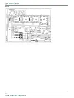
Page 101: ...inversion on the bus DS5 Isolated supply for communication DS7 RUN One flash per second DS8 TxD to flasher system Normally OFF Lights up momentarily during transmission or reception If one of these LEDs is permanently OFF there is no traffic on the corresponding bus DS9 RxD from flasher system If one of these LEDs is permanently ON there may be polarity inversion on the bus 9 7 Wiring diagrams FCU...

Page 102: ...FCU 3 Flashing System Maintenance PCB drawings and settings 92 Copyright ADB Safegate All Rights Reserved ...

Page 103: ...trol and monitoring Multiwire industrial field bus J Bus or the two combined Dimensions width x depth x height mm inc sun roof and base 420 x 235 x 520 790 x 340 x 650 Weight kg 19 4 47 10 2 Ambient conditions Table 54 Ambient conditions Item Description Temperature From 20 up to 55 C Altitude From 0 sea level up to 1000 meters Relative humidity From 10 RH up to 95 RH without dewing 10 3 Parts lis...

Page 104: ...ith housing 6341 80 230 1 Door micro switch 6150 49 010 1 Main power phase terminal 16 mm2 6112 45 170 10 Main power neutral terminal 16 mm2 6112 45 175 10 Earth terminal 6112 45 007 10 Screw terminal connector PC 6 6 ST 10 16 for the cable between the fitting and the FCU 6112 32 440 10 Spring clamp terminal box 12 pole 6112 33 112 10 Spring clamp terminal box 6 pole 6112 32 518 10 Cage clamp 3 po...

Page 105: ...20 wires for multiwire 3229 13 030 1 Flat cable 20 wires for J bus 3229 13 020 1 PCB1502 J Bus interface 1590 03 490 1 Temperature sensor 1440 21 000 1 10 3 4 Optional parts Description Part number Quantity per order Mounting system for FCU1 and UEL including Mounting flange Tube 60 mm OD 800 mm high Flexible conduit Nipple for flexible conduit 1440 20 200 1 Over voltage protection cartridge for s...

Page 106: ...Flashing System Maintenance Technical data 96 Copyright ADB Safegate All Rights Reserved ...

Page 107: ...rt then company name prefer customer id number Contact phone number and email address Product with part number preferable or product number Have you reviewed the product s manual and troubleshooting guide Do you have a True RMS meter available and any other necessary tools Be located with the product ready to troubleshoot Note For more information see www adbsafegate com or contact ADB SAFEGATE Su...

Page 108: ... parts which are fully removed separated from any customer equipment and returned will be accepted for our recycling program All items returned must be clearly labelled as follows For ROHS WEEE Recycling Sender contact information Name Business Address Phone number Main Unit Serial Number ADB SAFEGATE will continue to monitor and update according for any future requirements for EU directives as an...

Page 109: ... 40 699 17 00 Fax 46 0 40 699 17 30 Email marketing adbsafegate com Internet www adbsafegate com ADB SAFEGATE Airfield Technologies Ltd China ADB SAFEGATE China Unit 603 D Block CAMIC International Convention Center No 3 Hua Jia Di East road ChaoYang district Beijing 100102 P R China Contact Tel 86 10 8476 0106 Fax 86 10 8476 0090 Email china safegate com Internet www adbsafegate com ADB SAFEGATE ...

Page 110: ......
Reviews: