


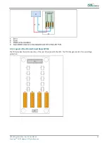


Description:
•
P1: Bus A connection to the substation on the master;
•
P3: Bus B connection to the substation on the master;
•
P5: PE.
9.5.2 Connectors
Table 51: J-Bus connectors
Connector
Description
P1
Meant for the connection of Bus A from the previous user on the system.
P3
Meant for Bus B.
Table 52: Wiring for connectors P1-P4
Wire
Description
1
Tx +
2
Rx +
3
Tx -
4
Rx -
5
0V
6
PE
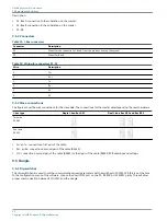
9.5.3 Slave connections
The figures show the wire connections for the slave side. The connections for the master side depend on the used hardware.
J-bus type
Single J-bus: Bus A P1
Dual J-bus: Bus A P1 and Bus B P3
Two wire
RS485
Four wire
RS422
•
Tx+ an Tx- connections: first pair of the cable;
•
Rx+ an Rx- connections: second pair of the cable (RS422);
•
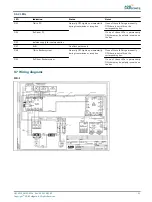
O V connections: second pair of the cable (RS485) or third pair of the cable (RS422).PCB drawings and settings
9.6 Dongle
9.6.1 Dip-switches
The dip-switch bank is used to set the communication speed parameters. Set the switches to 10101010 if this is not the case.
In the configuration menu of the software, choose the used COM port on the PC, ‘38400’ bd & ‘EVEN’ parity. This will allow
proper communication between FCU/ LMC and the dongle.
Flashing System Maintenance
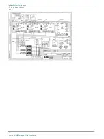
PCB drawings and settings
90
Copyright
©
ADB Safegate, All Rights Reserved
Summary of Contents for FCU-1-in-1
Page 2: ......
Page 8: ...Flashing System Maintenance TABLE OF CONTENTS viii Copyright ADB Safegate All Rights Reserved ...
Page 18: ...Flashing System Maintenance Safety 8 Copyright ADB Safegate All Rights Reserved ...
Page 28: ...Flashing System Maintenance Introduction 18 Copyright ADB Safegate All Rights Reserved ...
Page 42: ...Flashing System Maintenance Commissioning 32 Copyright ADB Safegate All Rights Reserved ...
Page 64: ...Flashing System Maintenance Maintenance 54 Copyright ADB Safegate All Rights Reserved ...
Page 106: ...Flashing System Maintenance Technical data 96 Copyright ADB Safegate All Rights Reserved ...
Page 110: ......