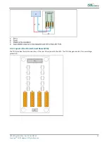
The illustration shows the connections on TB2 (A to E) and the pin-hole numbers on the receptacle for a FFL type flasher head
(F)
•
A: Cab-
•
B: Cab+
•
C: PE
•
D: +400 V
•
E: TRIG
9.1.3 Straps
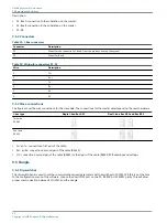
The straps are used to terminate the local bus, where necessary.
To set the resistors, set the straps as follows:
Table 34: FCU straps
Strap
Bus use
Resistor 680 Ohm
Terminating resistor 150 Ohm
Pull up
Pull down
W11
Local bus
x
W28
x
W25
x
Table 35: Resistor settings
Resistor [E]
Description
150
Terminates the bus.
680
There is always two types of 680 E resistors:
•
Pull-up resistor on the positive bus wire;
•
Pull-down resistor on the negative wire.
9.1.4 Dip-switches
CAUTION
Restart the equipment after you change the switch settings. The changes only become effective after you restart the
equipment.
UM-4019_AM02-620e, Rev. 3.0, 2020/05/12
77
Copyright
©
ADB Safegate, All Rights Reserved
Summary of Contents for FCU-1-in-1
Page 2: ......
Page 8: ...Flashing System Maintenance TABLE OF CONTENTS viii Copyright ADB Safegate All Rights Reserved ...
Page 18: ...Flashing System Maintenance Safety 8 Copyright ADB Safegate All Rights Reserved ...
Page 28: ...Flashing System Maintenance Introduction 18 Copyright ADB Safegate All Rights Reserved ...
Page 42: ...Flashing System Maintenance Commissioning 32 Copyright ADB Safegate All Rights Reserved ...
Page 64: ...Flashing System Maintenance Maintenance 54 Copyright ADB Safegate All Rights Reserved ...
Page 106: ...Flashing System Maintenance Technical data 96 Copyright ADB Safegate All Rights Reserved ...
Page 110: ......


