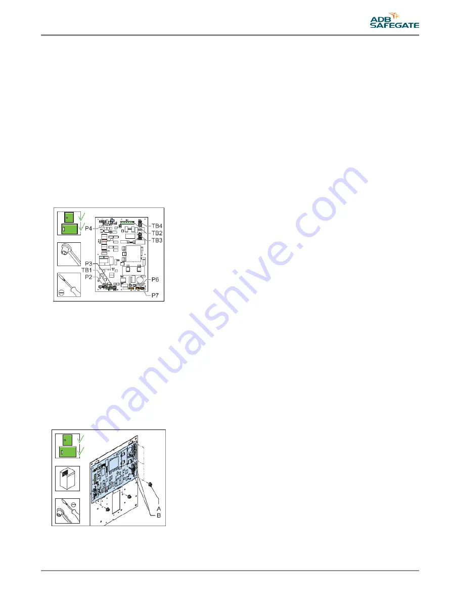
17. Connect the cables to the connectors:
•
Power supply to the DC unit to P7 (left-hand FCU PCB only);
•
Power supply to P6 (If necessary to identify the connector, measure for 230 V);
•
MOV connection to P3;
•
Power distribution from the DC unit to TB1;
•
Door switch to P2;
•
Capacitor terminal connection to TB3 (red wire to +400 and blue/white wire to PE);
•
Coil connection to TB4 (RET and TRIG). The polarity is not important ;
•
Flasher head connection to TB2;
•
Local bus to P4;
18. Install the cover.
19. Close the cabinet door.
20. Check if the FCU PCB works correctly. See
.
5.2.4 FCU-1 PCB or FCU-3 middle PCB
The procedure applies to the PCB of the FCU-1 and the middle PCB of the FCU-3.
Remove
1. Make sure that all power to the equipment is OFF. See §
Prepare: Switch OFF power supply
.
2. Remove the cover. See §
.
3. Disconnect all the connectors on the PCB. Use pliers for the connectors in TB3 , if necessary .
4. Loosen the nine nuts (A).
5. Loosen the two screws (B).
6. Remove the PCB. Use a lever under the board, if necessary .
Install - 1
UM-4019_AM02-620e, Rev. 3.0, 2020/05/12
37
Copyright
©
ADB Safegate, All Rights Reserved
Summary of Contents for FCU-1-in-1
Page 2: ......
Page 8: ...Flashing System Maintenance TABLE OF CONTENTS viii Copyright ADB Safegate All Rights Reserved ...
Page 18: ...Flashing System Maintenance Safety 8 Copyright ADB Safegate All Rights Reserved ...
Page 28: ...Flashing System Maintenance Introduction 18 Copyright ADB Safegate All Rights Reserved ...
Page 42: ...Flashing System Maintenance Commissioning 32 Copyright ADB Safegate All Rights Reserved ...
Page 64: ...Flashing System Maintenance Maintenance 54 Copyright ADB Safegate All Rights Reserved ...
Page 106: ...Flashing System Maintenance Technical data 96 Copyright ADB Safegate All Rights Reserved ...
Page 110: ......


