


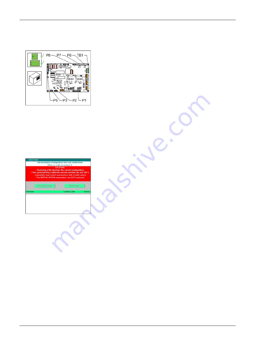
•
Local bus to P2;
•
J-Bus connection to P1 (optional).
12. When you configured the flashing system with the configuration software tool, reload the settings.
13. Close the cabinet door.
Restore IO profile
14. Switch ON the equipment.
15. Open the configuration software tool.
16. Go to menu SAVE .
17. Restore the IO profile.
Select Restore and browse to the saved profile on your PC.
18. Switch OFF all power to the equipment. See §
Prepare: Switch OFF power supply
Configure
19. Configure the flashing system. See §
.
5.2.6 Multiwire PCB
The procedure applies to both 24 V DC and 48 V DC type of multiwire PCBs.
Replace
1. Make sure that all power to the equipment is OFF. See §
Prepare: Switch OFF power supply
2. Disconnect the cables from the multiwire PCB (B).
3. Remove the nuts (A). Use a number 5.5 socket wrench.
4. Replace the multiwire PCB (B).
5. Set the straps to the same settings as the old multiwire PCB .
6. Install the nuts (A). Use a number 5.5 socket wrench.
Flashing System Maintenance
Maintenance
40
Copyright
©
ADB Safegate, All Rights Reserved
Summary of Contents for FCU-1-in-1
Page 2: ......
Page 8: ...Flashing System Maintenance TABLE OF CONTENTS viii Copyright ADB Safegate All Rights Reserved ...
Page 18: ...Flashing System Maintenance Safety 8 Copyright ADB Safegate All Rights Reserved ...
Page 28: ...Flashing System Maintenance Introduction 18 Copyright ADB Safegate All Rights Reserved ...
Page 42: ...Flashing System Maintenance Commissioning 32 Copyright ADB Safegate All Rights Reserved ...
Page 64: ...Flashing System Maintenance Maintenance 54 Copyright ADB Safegate All Rights Reserved ...
Page 106: ...Flashing System Maintenance Technical data 96 Copyright ADB Safegate All Rights Reserved ...
Page 110: ......