40
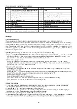
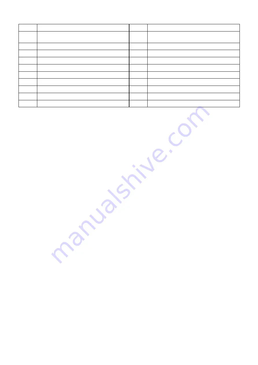
The control system has the following functions:
S/N
Function
S/N
Function
1
Controlling the 2-way valve of the water system (relevant
accessories need to be purchase separately);
11
Timing
2
Anti-freeze protection for plate heat exchanger
12
Protection for Compressors in Operation
3
Alternative defrosting
13
Averaging Workload among Compressors
4
Manual defrosting
14
Failure alarm, viewing and output
5
2-way Valve Interlock Control
15
Memorizing parameters in the case of a power failure
6
Week Setting
16
Setting and resetting the operating parameters of the unit
7
Status display
17
Electric heater
8
Auto-startup at power on
18
Setting the clock of the system
9
Setting the serial number of a unit
19
Displaying the indoor and inlet water temperatures
10
Memorizing the clock settings in the case of a power failure
Settings
1) Parameter Viewing
The controller can be used to view the operation status and parameters of any unit connected to it.
Parameters can be view include operation status of the compressor, inlet/outlet water temperature, timer setting,
cooling antifreeze temperature setting, antifreeze temperature setting in winter, defrosting temperature, and so on.
After pressing the "UNIT" key, you can increase/decrease the blinking unit No. and view the parameters of the
current unit by pressing
"▲"
or
"▼".
To view more working parameters of a unit, you can press "OK" and
"▲"
or
"▼" after reaching the unit No.
2) Setting Parameters (parameters can be set only when the unit is turned off)
①
Upon pressing the "PASSWORD", bottom of the LCD will display "Input password" and "___". Use the “▲” or “▼”
to key in the number. Press "OK" after key in the correct password (factory default password is "0055"). If the
password key in is correct, the led will blinks parameters that can be set.
②
③
How to change password:
After key in the correct password, press the "PASSWORD" button once more. The LED should
display "__" and new password can set using the “▲” or “▼” key. Upon reaching the number which
you desire, press the "OK" button to confirm.
How to set the parameter:
Press the "UNIT" button then “▲” or “▼” to browse through the units within the system (Depends on system).
Press "OK" once confirm.
Press “▲” or “▼” to browse through the parameters that can be set (including the inlet/outlet water temperature).
Press "OK" once confirm to view and change the parameter by using the “▲” or “▼”.
Press "OK" once again to confirm.
Repeat this step to change other parameters.
(Note: The controller will prompt for password again if no key is pressed within 60 seconds.)
(Note: Parameter can only be set when the unit is in standby mode)
3) Real Time Setting
1 To set week and time, press the small hole above the "Mode" key using a needle-like tool (the LCD displays "
Weekday Setting" indicating access to the weekday adjustment phase).
2 Press the “▲” or “▼” key to set the weekday of the current time.
3 Press the small button again to save the weekday setting. Meanwhile, the “Time Setting” text will be displayed
and blinks on the LCD indicating access to the time adjustment phase.
4 Press the “▲” key to change hour, and the “▼” key to change minute.
5 Press the small button again to save the set time. Note: If the “Unit”, “Password”, “Timer” or “Enter” key is pressed
or no key is pressed within 5s during setting process, time setting will exit without saving the set time.
Summary of Contents for A5MAC 210D
Page 1: ...Technical Manual AIR COOLED MODULAR CHILLER A5MAC 210D A5MAC 230D A5MAC 340D A5MAC 450D...
Page 14: ...14 Wiring Diagrams MODEL A5MAC210 230D...
Page 15: ...16 1 4 5 3 2 7 8 6 1 4 5 3 2 7 8 6 A5MAC340DR...
Page 16: ...17 1 4 5 3 2 7 8 6 1 4 5 3 2 7 8 6 A5MAC450D...
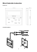
Page 36: ...38 Wired Controller Instruction Dimensions Controller Installation...


