background image

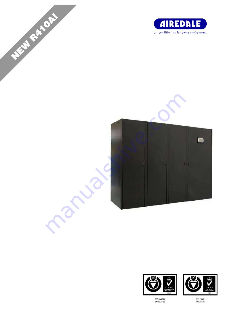
SmartCool™

Downflow – Precision Air Conditioning

R410A

I n s t a l l a t i o n ,   M a i n t e n a n c e a n d

C o m m i s s i o n i n g

Summary of Contents for SmartCool C000

Page 1: ...SmartCool Downflow Precision Air Conditioning R410A Installation Maintenance and Commissioning ...

Page 2: ...o maintenance being carried out in accordance with the recommendations provided during the warranty period Failure to have the maintenance procedures carried out will invalidate the warranty and any liabilities by Airedale International Air Conditioning Ltd Spares A spares list for 1 3 and 5 years will be supplied with every unit and is also available from our Spares department on request Training...

Page 3: ...aged Unit Pre Charged Refrigerant Volumes 21 Design Data Water Cooled Free Cooling 22 System Pressure Strength Test 23 System Leak Test 23 Evacuation 24 Refrigerant Handling 25 Oil Charging Guide 26 Pressure switch settings 26 Compressor Oil Information 27 Chilled Water System 29 Humidification 29 Condensate Drain Pipework 32 Fitting Instructions 33 Pipe Clips 33 Condensate Drain Priming 33 Checki...

Page 4: ...ing Wiring W2W2 103 Water Cooled and Chilled Water models W2C0 105 Performance Data Water Cooled Chilled Water Models 105 Mechanical Data W2C0 107 Electrical Data W2C0 113 Sound Data W2C0 119 Waterside Pressure Drops W2C0 120 Interconnecting Wiring W2C0 122 Water Cooled and Free Cooling W2F0 124 Performance Data Water Cooled Free Cooling 124 Mechanical Data W2F0 126 Electrical Data W2F0 132 Sound ...

Page 5: ...hange 177 Evaporator Fan removal 178 Troubleshooting Indoor Unit 179 Suction throttle valve STV 181 Hot Gas Re heat HGRH 181 Humidifier 181 Unit Alarms 182 Specifier s Guide Outdoor unit 190 Unit Identification 190 Standard Features 191 Optional Extras Energy Saving 193 Installation data 194 Dimensions Weights Positioning 194 Unit Lifting 199 Re orientation to Vertical Discharge 200 Positioning 20...

Page 6: ... confined or poorly ventilated areas 6 A full hazard data sheet in accordance with COSHH regulations is available should this be required Protective personal equipment Airedale recommends that personal protective equipment is used whilst installing maintaining and commissioning equipment Refrigerant Warning The Airedale SmartCool uses R410A refrigerant which is a high pressure refrigerant It requi...

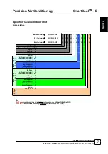
Page 7: ... 150 Separator Air Cooled Comp Indoor X Water Cooled Comp Indoor W Chilled Water C No Compressor 0 Single Compressor 1 Tandem Compressor 2 Inverter Compressor V No Option 0 Air Cooled Comp Indoor X Water Cooled Comp Indoor W Free Cooling F Chilled Water C No Compressor 0 Single Compressor 1 Tandem Compressor 2 Inverter Compressor V Seperator 400V 3PH 50Hz 0 Note Dual Cool units are defined as thos...

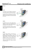
Page 8: ...odel types and capacities to be installed side by side The flexibility of this type of installation provides for multi circuit functionality A full range of air cooled condensers is available with the direct expansion indoor units to provide a matched system with optional performance upgrade refer to Outdoor Unit A full range of Dry coolers is available to complement the free cooling indoor units ...

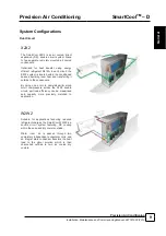
Page 9: ...pace absorbing room heat and transferring it outside to the condensers By using one or more same dissimilar sized scroll compressors across the X2X2 double circuit part load efficiency can be maximised and capacity more precisely matched to application W2W2 Suitable for applications favouring reduced refrigerant charges the SmartCool W2W2 is a double circuit system featuring DX cooling within the ...

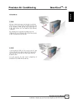
Page 10: ...ng mediums within the same case DX water cooled as in the W2W2 system and chilled water as in the C000 system The Airetronix microprocessor elects which medium acts as the primary source of cooling and which as back up if the primary source fails or is unable to cope with the heat load W2F0 The W2F0 system includes a free cooling coil in conjunction with the evaporator In low ambient conditions pa...

Page 11: ...ansferred to a chilled water system such as Airedale s high efficiency TurboChill By controlling the 3 way water regulating valve the intelligent Airetronix microprocessor can achieve precise control of temperature and humidity C0C0 In the SmartCool C0C0 unit the cooling coils are split into two independent systems each with a 3 way water regulating valve and cooled by chilled water from two separ...

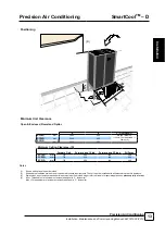
Page 12: ...lable as standard on all products Does not require configuring 2 Area denotes services entry location For specific details please contact Airedale 3 Open base Shaded area denotes air discharge 4 M6 fixing holes positions for mounting ceiling duct extensions or plenums Packed Dimensions For specific markets units shall be shipped mounted on wooden pallet and covered with polythene The pallet shall ...

Page 13: ...Side Forward and 2 Sides All Faces SC19D mm 720 500 380 250 SC25D mm 740 550 440 280 SC31D mm 750 590 480 300 Notes 1 Shown with optional open floor stand 2 Shaded area indicates minimum service and maintenance requirements The unit must be installed with allowance for carpet tile clearance 3 Dimension C denotes recommended minimum maximum floor stand height refer to Airedale for special applicati...

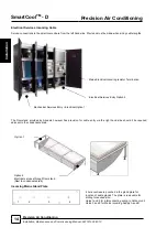
Page 14: ...ia the right hand side should it be required adjacent to the condensate drain Incoming Mains Gland Plate 4 hole centres are punched in the gland plate for location of cable glands The plate is removable for drilling to required size Holes1 and 2 for interconnecting wiring to Outdoor unit Holes 3 and 4 for Mains incoming Supply A and B Mains Electrical Incoming Isolator Termination Mechanical Servi...

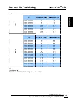
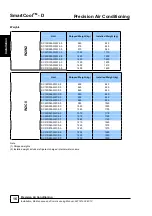
Page 15: ...00 1310 X2C0 Unit Shipped Weight kg Installed Weight kg SC19D033 X2C0 0 820 860 SC19D038 X2C0 0 820 860 SC19D045 X2C0 0 820 860 SC19D064 X2C0 0 890 920 SC19D070 X2C0 0 900 930 SC19D076 X2C0 0 900 930 SC25D045 X2C0 0 940 980 SC25D050 X2C0 0 990 1030 SC25D055 X2C0 0 1000 1040 SC25D067 X2C0 0 1010 1050 SC25D073 X2C0 0 1010 1060 SC25D080 X2C0 0 1020 1060 SC31D055 X2C0 0 1150 1200 SC31D065 X2C0 0 1150 ...

Page 16: ...0 1420 W2C0 Unit Shipped Weight kg Installed Weight kg SC19D033 W2C0 0 850 880 SC19D038 W2C0 0 860 890 SC19D045 W2C0 0 860 890 SC19D064 W2C0 0 950 980 SC19D070 W2C0 0 950 980 SC19D076 W2C0 0 960 990 SC25D045 W2C0 0 980 1020 SC25D050 W2C0 0 1050 1090 SC25D055 W2C0 0 1050 1100 SC25D067 W2C0 0 1070 1110 SC25D073 W2C0 0 1070 1120 SC25D080 W2C0 0 1080 1120 SC31D055 W2C0 0 1210 1260 SC31D065 W2C0 0 1220...

Page 17: ...31D075 W2F0 0 1220 1270 SC31D077 W2F0 0 1230 1280 SC31D080 W2F0 0 1230 1280 SC31D083 W2F0 0 1230 1290 C000 Unit Shipped Weight kg Installed Weight kg SC19D065 C000 0 725 780 SC19D075 C000 0 725 780 SC19D090 C000 0 730 780 SC25D090 C000 0 840 920 SC25D100 C000 0 840 920 SC25D110 C000 0 840 920 SC31D110 C000 0 1000 1080 SC31D130 C000 0 1000 1080 SC31D150 C000 0 1000 1080 C0C0 Unit Shipped Weight kg ...

Page 18: ...8 3 4 1 1 8 1 1 8 SC31D075 X2C0 0 CR105 7 8 1 3 8 3 4 1 1 8 1 1 8 7 8 1 1 8 1 1 8 SC31D077 X2C0 0 CR105 7 8 1 3 8 3 4 1 1 8 1 1 8 7 8 1 3 8 1 1 8 SC31D080 X2C0 0 CR105 7 8 1 3 8 3 4 1 1 8 1 1 8 7 8 1 3 8 1 1 8 SC31D083 X2C0 0 CR105 7 8 1 3 8 3 4 1 1 8 1 1 8 7 8 1 3 8 1 1 8 1 For interconnecting pipework with a predominantly horizontal layout 2 For interconnecting pipework with a predominantly vert...

Page 19: ...for the indoor and outdoor units Indoor Unit Standard Condenser Larger Condenser Indoor Unit kg Circuit HGRH 1 kg Circuit Outdoor Unit kg Circuit Outdoor Unit kg Circuit SC19D055 X2X2 4 41 4 56 CR50 4 9 CR65 9 78 SC19D070 X2X2 4 66 4 81 CR65 9 78 CR80 8 37 SC19D080 X2X2 4 66 4 81 CR65 9 78 CR80 8 37 SC25D080 X2X2 5 84 6 04 CR65 9 78 CR80 8 37 SC25D090 X2X2 6 37 6 60 CR65 9 78 CR80 8 37 SC25D100 X2...

Page 20: ...Calculation of Liquid Line Refrigerant Charge kg The liquid line refrigerant charge can be calculated using the following equation LR L x m Where LR Total Liquid Line Refrigerant charge kg L Length of Interconnecting pipework metres m Liquid Line Refrigerant charge metre Refer to Liquid Line Refrigerant Charge kg m above Calculation of System Refrigerant Charge kg The system refrigerant charge can...

Page 21: ...Therefore liquid sub cooling required to prevent liquid flashing 2 4 C Packaged Unit Pre Charged Refrigerant Volumes Indoor unit kg circuit HGRH kg circuit Indoor unit kg circuit HGRH kg circuit SC19D055 W2W2 5 75 5 90 SC19D033 W2F0 5 68 5 83 SC19D070 W2W2 7 32 7 47 SC19D038 W2F0 7 25 7 40 SC19D080 W2W2 7 32 7 47 SC19D045 W2F0 7 25 7 40 SC25D080 W2W2 8 51 8 70 SC19D064 W2F0 9 60 9 81 SC25D090 W2W2...

Page 22: ...e drop graph Where Ps Maximum Water Glycol Pressure Drop for the indoor unit kPa Pw Equivalent Water Pressure Drop for indoor unit kPa Pχ Glycol Pressure Drop Correction Factor 20 C Water Temperature Refer to table below The resultant pressure drop Ps is the maximum pressure drop based on the indoor unit running at the prescribed conditions This will typically occur when the water glycol temperatu...

Page 23: ... hour A longer period may be appropriate for larger systems or a fall in pressure due to leaks may not be detected Any fall in pressure indicates a leak which should be traced System Leak Test The system leak test is carried out with the low pressure transducers and switches fitted Leak Pressure Test is the pressure applied to a refrigeration system or part of a system to test for leakage This tes...

Page 24: ...ntil a pressure of 1 5 Torr 200 Pa absolute pressure is reached at which time the vacuum pump should be stopped and the vacuum broken with oxygen free nitrogen until the pressure rises above zero 4 The above operation should be repeated a second time 5 The system should then be evacuated a third time but this time to 0 5 Torr absolute pressure and broken with the correct refrigerant until pressure...

Page 25: ...and operating temperatures Pipework runs must be taken into consideration The refrigerant charge must be weighed into the system and recorded within your F Gas record RECORD Record on commissioning sheet provided once completed IMPORTANT It is important that solenoid valves are energised correctly to ensure that the Hot Gas ReHeat coil is broken of vacuum the Normally Closed NC valve should be ene...

Page 26: ...ng the oil return in the system is insufficient A pipework design check is required IMPORTANT It is possible to check the oil level of a compressor a few moments after it is turned off However the oil level must not be observed when the compressor is turned off The refrigerant in the system can give a false indication of this level In this case the oil level should be at about 1 3 IMPORTANT For ap...

Page 27: ...1 57 1 57 37 2 37 2 SC19D045 X2C0 1 57 1 57 37 2 37 2 SC19D064 X2C0 3 3 3 3 67 67 Yes POE 160SZ Internal Discharge Gas Thermostat Opens 135 C Yes SC19D070 X2C0 3 3 3 3 69 69 SC19D076 X2C0 3 6 3 3 72 72 SC25D045 X2C0 1 57 1 57 37 2 37 2 Yes PVE Lubricant 320HV Internal Thermodisc No SC25D050 X2C0 3 3 58 58 Yes POE 160SZ Internal Discharge Gas Thermostat Opens 135 C Yes SC25D055 X2C0 3 3 58 58 SC25D...

Page 28: ... W2C0 3 3 58 58 SC25D067 W2C0 3 3 3 3 69 69 SC25D073 W2C0 3 3 3 3 69 69 SC25D080 W2C0 3 6 3 6 72 72 SC31D055 W2C0 3 3 58 58 SC31D065 W2C0 3 3 3 3 64 2 64 2 SC31D075 W2C0 3 3 3 3 64 2 64 2 SC31D077 W2C0 3 3 3 3 69 69 SC31D080 W2C0 3 3 3 6 69 72 SC31D083 W2C0 3 6 3 6 72 72 W2F0 SC19D033 W2F0 1 57 1 57 37 2 37 2 Yes PVE Lubricant 320HV Internal Thermodisc No SC19D038 W2F0 1 57 1 57 37 2 37 2 SC19D045...

Page 29: ...the conditioned area and corrosive salts and minerals are held in the disposable bottle The steam shall be distributed through a sparge pipe fitted to the coil assembly Featuring modulating capacity output control as standard the system shall provide continuous modulation of steam output in response to a proportional control signal The output control shall range is 20 100 of the humidifier rated v...

Page 30: ...ides ppm Cl 0 20 Silica mg l SiO2 0 20 Residual chlorine mg l Cl 0 0 2 Calcium sulphate mg l CaSO4 0 60 Metallic impurities mg l 0 0 Solvents diluents soaps lubricants mg l 0 0 1 Values depending on specific conductivity in general TDS 0 93 σ20 R180 0 65 σ20 2 not lower than 200 of the chloride content in mg l of Cl 3 not lower than 300 of the chloride content in mg l of Cl Warning no relation can...

Page 31: ...d with the standard conductivity cylinder which shall cover the majority of water supplies Where the water conductivity is known please specify at order For further details please contact Airedale CAUTION The supply water pressure to the humidifier assembly must be between 1 8 barg Safe Operation of Humidifier To protect the humidifier bottle from dangerous pressures in event of the steam supply p...

Page 32: ...3 8 tube MUST BE copper tube when coupled with humidifier drain minimum fall 1 20 Condensate Humidifier Optional Extra All drain trays are fitted with their own trap assembly Condensate drain may be run to waste via ordinary plastic waste pipe Humidifier drain may be run to waste via pipe suitable for liquid temperatures of 100 C All drain pipework operating under gravity should be sloped away fro...

Page 33: ...icted condensate flow from the condensate and humidifier drain The pipework fitted is connected to the condensate drain with a compression fitting The pipework locates into the pump through grommet holes Pipe Clips The flexible pipework clips are to be tightened sufficiently to maintain a water tight seal during unit operation Do not over tighten as this can damage the condensate hose Condensate D...

Page 34: ...d pressure differential It is the responsibility of the installer to fit the air pressure sensor s The sensor shall be located under the false floor with the 6mm flamtronix tubing routed back into the control panel of the unit the tubing must not be obstructed damaged to ensure accurate pressure control The constant pressure system shall be commissioned by Airedale following routing of tubing from...

Page 35: ...19D STD 5 06 9 4 9 6 9 7 9 9 2 53 4 8 5 1 5 4 5 6 5 9 6 1 6 4 6 7 6 9 7 2 7 3 7 5 5 50 EC SC19D UPG 5 06 8 9 9 0 9 1 9 2 9 4 9 5 9 6 9 7 9 8 9 9 2 53 4 4 4 8 5 1 5 3 5 5 5 7 5 9 6 1 6 3 6 5 6 7 6 9 5 50 9 6 9 7 9 8 9 9 SC19D100 C000 0 EC SL19D STD 5 06 9 3 9 5 9 6 9 8 9 9 2 53 4 8 5 0 5 3 5 6 5 8 6 1 6 3 6 6 6 9 7 1 7 3 7 5 5 70 EC SL19D UPG 5 06 8 8 8 9 9 0 9 2 9 3 9 4 9 5 9 6 9 7 9 8 9 9 2 53 4 ...

Page 36: ...9 7 9 8 9 9 Model Fan Selection Standard Air Volume m s DeHum Air Volume m s Max Air Volume m s External Static Pressure Pa 25 50 75 100 125 150 175 200 225 250 275 300 SC25D100 C000 0 AC SC25D STD 5 91 8 8 9 0 9 2 9 3 9 5 9 7 9 8 2 96 4 6 5 0 5 3 5 5 5 8 6 0 6 2 6 4 6 7 6 9 7 1 7 3 7 75 EC SC25D STD 5 91 8 2 8 4 8 5 8 7 8 9 9 0 9 2 9 3 9 5 9 7 9 8 2 96 4 3 4 6 4 9 5 2 5 5 5 8 6 1 6 4 6 6 6 9 7 2 ...

Page 37: ...3 7 75 EC SC25D STD 5 91 8 2 8 4 8 5 8 7 8 9 9 0 9 2 9 3 9 5 9 7 9 8 2 96 4 3 4 6 4 9 5 2 5 5 5 8 6 1 6 4 6 6 6 9 7 2 7 4 7 75 EC SC25D UPG 5 91 7 7 7 8 7 9 8 1 8 2 8 4 8 5 8 6 8 8 8 9 9 1 9 2 2 96 4 0 4 3 4 6 4 9 5 2 5 4 5 6 5 8 6 0 6 3 6 5 6 7 7 75 9 9 SC25D055 C0C0 0 AC SC25D STD 6 50 9 7 9 9 3 25 5 1 5 4 5 6 5 9 6 1 6 3 6 5 6 8 7 0 7 2 7 4 7 6 7 75 EC SC25D STD 6 50 9 0 9 1 9 3 9 4 9 6 9 8 9 9...

Page 38: ...9 8 10 0 2 22 4 3 4 6 4 9 5 2 5 4 5 7 6 0 6 3 6 5 6 8 7 1 7 3 5 50 EC SC19D UPG 4 43 7 8 8 0 8 1 8 2 8 3 8 5 8 6 8 7 8 8 9 0 9 1 9 2 2 22 3 8 4 2 4 5 4 8 5 1 5 3 5 5 5 8 6 0 6 2 6 4 6 6 5 50 9 6 9 7 9 8 9 9 SC19D080 X2X2 0 EC SC19D STD 5 06 9 4 9 6 9 7 9 9 2 53 4 8 5 1 5 4 5 6 5 9 6 1 6 4 6 7 6 9 7 2 7 3 7 5 5 50 EC SC19D UPG 5 06 8 9 9 0 9 1 9 2 9 4 9 5 9 6 9 7 9 8 9 9 2 53 4 4 4 8 5 1 5 3 5 5 5 ...

Page 39: ...0 9 1 2 93 3 9 4 3 4 6 4 9 5 1 5 4 5 6 5 8 6 0 6 2 6 4 6 7 7 75 9 9 SC25D100 X2X2 0 AC SC25D STD 6 50 9 7 9 9 3 25 5 1 5 4 5 6 5 9 6 1 6 3 6 5 6 8 7 0 7 2 7 4 7 6 7 75 EC SC25D STD 6 50 9 0 9 1 9 3 9 4 9 6 9 8 9 9 3 25 4 7 5 0 5 3 5 5 5 8 6 1 6 4 6 6 6 9 7 2 7 4 7 5 7 75 EC SC25D UPG 6 50 8 4 8 5 8 7 8 8 8 9 9 1 9 2 9 3 9 4 9 6 9 7 9 8 3 25 4 3 4 6 5 0 5 2 5 4 5 6 5 8 6 1 6 3 6 5 6 7 6 9 7 75 9 9 ...

Page 40: ... 5 6 5 8 6 1 6 3 6 5 6 7 6 9 7 75 EC SC25D STD 5 20 7 3 7 5 7 7 7 8 8 0 8 2 8 4 8 5 8 7 8 9 9 0 9 2 2 60 3 9 4 2 4 5 4 8 5 1 5 4 5 7 6 0 6 3 6 6 6 9 7 2 7 75 EC SC25D UPG 5 20 6 8 7 0 7 1 7 3 7 5 7 6 7 8 7 9 8 1 8 2 8 4 8 5 2 60 3 6 3 9 4 2 4 6 4 9 5 1 5 3 5 6 5 8 6 0 6 2 6 4 7 75 9 9 SC25D090 W2W2 0 AC SC25D STD 5 85 8 8 8 9 9 1 9 3 9 4 9 6 9 8 9 9 2 93 4 6 4 9 5 3 5 5 5 7 6 0 6 2 6 4 6 6 6 8 7 1...

Page 41: ... 5 7 5 9 6 1 6 3 6 5 5 50 9 6 9 7 9 8 9 9 SC19D045 X2C0 0 EC SC19D STD 5 06 9 4 9 6 9 7 9 9 2 53 4 8 5 1 5 4 5 6 5 9 6 1 6 4 6 7 6 9 7 2 7 3 7 5 5 50 EC SC19D UPG 5 06 8 9 9 0 9 1 9 2 9 4 9 5 9 6 9 7 9 8 9 9 2 53 4 4 4 8 5 1 5 3 5 5 5 7 5 9 6 1 6 3 6 5 6 7 6 9 5 50 9 6 9 7 9 8 9 9 SC19D064 X2C0 0 EC SC19D STD 5 06 9 4 9 6 9 7 9 9 2 53 4 8 5 1 5 4 5 6 5 9 6 1 6 4 6 7 6 9 7 2 7 3 7 5 5 50 EC SC19D U...

Page 42: ...6 5 6 8 7 0 7 2 7 4 7 6 7 75 EC SC25D STD 6 50 9 0 9 1 9 3 9 4 9 6 9 8 9 9 3 25 4 7 5 0 5 3 5 5 5 8 6 1 6 4 6 6 6 9 7 2 7 4 7 5 7 75 EC SC25D UPG 6 50 8 4 8 5 8 7 8 8 8 9 9 1 9 2 9 3 9 4 9 6 9 7 9 8 3 25 4 3 4 6 5 0 5 2 5 4 5 6 5 8 6 1 6 3 6 5 6 7 6 9 7 75 9 9 SC25D073 X2C0 0 AC SC25D STD 6 50 9 7 9 9 3 25 5 1 5 4 5 6 5 9 6 1 6 3 6 5 6 8 7 0 7 2 7 4 7 6 7 75 EC SC25D STD 6 50 9 0 9 1 9 3 9 4 9 6 9...

Page 43: ... 7 5 5 50 EC SC19D UPG 5 06 8 9 9 0 9 1 9 2 9 4 9 5 9 6 9 7 9 8 9 9 2 53 4 4 4 8 5 1 5 3 5 5 5 7 5 9 6 1 6 3 6 5 6 7 6 9 5 50 9 6 9 7 9 8 9 9 SC19D070 W2C0 0 EC SC19D STD 5 06 9 4 9 6 9 7 9 9 2 53 4 8 5 1 5 4 5 6 5 9 6 1 6 4 6 7 6 9 7 2 7 3 7 5 5 50 EC SC19D UPG 5 06 8 9 9 0 9 1 9 2 9 4 9 5 9 6 9 7 9 8 9 9 2 53 4 4 4 8 5 1 5 3 5 5 5 7 5 9 6 1 6 3 6 5 6 7 6 9 5 50 9 6 9 7 9 8 9 9 SC19D076 W2C0 0 EC...

Page 44: ... 0 9 1 9 3 9 4 9 6 9 8 9 9 3 25 4 7 5 0 5 3 5 5 5 8 6 1 6 4 6 6 6 9 7 2 7 4 7 5 7 75 EC SC25D UPG 6 50 8 4 8 5 8 7 8 8 8 9 9 1 9 2 9 3 9 4 9 6 9 7 9 8 3 25 4 3 4 6 5 0 5 2 5 4 5 6 5 8 6 1 6 3 6 5 6 7 6 9 7 75 9 9 SC25D080 W2C0 0 AC SC25D STD 6 50 9 7 9 9 3 25 5 1 5 4 5 6 5 9 6 1 6 3 6 5 6 8 7 0 7 2 7 4 7 6 7 75 EC SC25D STD 6 50 9 0 9 1 9 3 9 4 9 6 9 8 9 9 3 25 4 7 5 0 5 3 5 5 5 8 6 1 6 4 6 6 6 9 ...

Page 45: ... 7 5 5 50 EC SC19D UPG 5 06 8 9 9 0 9 1 9 2 9 4 9 5 9 6 9 7 9 8 9 9 2 53 4 4 4 8 5 1 5 3 5 5 5 7 5 9 6 1 6 3 6 5 6 7 6 9 5 50 9 6 9 7 9 8 9 9 SC19D070 W2F0 0 EC SC19D STD 5 06 9 4 9 6 9 7 9 9 2 53 4 8 5 1 5 4 5 6 5 9 6 1 6 4 6 7 6 9 7 2 7 3 7 5 5 50 EC SC19D UPG 5 06 8 9 9 0 9 1 9 2 9 4 9 5 9 6 9 7 9 8 9 9 2 53 4 4 4 8 5 1 5 3 5 5 5 7 5 9 6 1 6 3 6 5 6 7 6 9 5 50 9 6 9 7 9 8 9 9 SC19D076 W2F0 0 EC...

Page 46: ... 9 1 9 3 9 4 9 6 9 8 9 9 3 25 4 7 5 0 5 3 5 5 5 8 6 1 6 4 6 6 6 9 7 2 7 4 7 5 7 75 EC SC25D UPG 6 50 8 4 8 5 8 7 8 8 8 9 9 1 9 2 9 3 9 4 9 6 9 7 9 8 3 25 4 3 4 6 5 0 5 2 5 4 5 6 5 8 6 1 6 3 6 5 6 7 6 9 7 75 9 9 SC25D0 80 W2F0 0 AC SC25D STD 6 50 9 7 9 9 3 25 5 1 5 4 5 6 5 9 6 1 6 3 6 5 6 8 7 0 7 2 7 4 7 6 7 75 EC SC25D STD 6 50 9 0 9 1 9 3 9 4 9 6 9 8 9 9 3 25 4 7 5 0 5 3 5 5 5 8 6 1 6 4 6 6 6 9 7...

Page 47: ...egend Centrifugal Fan Axial Fan Scroll Compressor Three Way Solenoid Valve Sight Glass Thermostatic Expansion Valve Filter Drier Normally Closed Solenoid Valve Check Valve Shut Off Valve Bypass Balancing Valve Three Way Regulating Valve Three Way regulating valve with head pressure control Bleed Valve Binder Point Liquid Receiver Plate Condenser Installation ...

Page 48: ...SmartCoolTM D Precision Air Conditioning 48 Precision Air Conditioning Installation Maintenance and Commissioning Manual 6877419 02 2013 X2X2 Installation ...

Page 49: ...Precision Air Conditioning SmartCoolTM D Precision Air Conditioning 49 Installation Maintenance and Commissioning Manual 6877419 02 2013 X2C0 Installation ...

Page 50: ...SmartCoolTM D Precision Air Conditioning 50 Precision Air Conditioning Installation Maintenance and Commissioning Manual 6877419 02 2013 W2W2 Installation ...

Page 51: ...Precision Air Conditioning SmartCoolTM D Precision Air Conditioning 51 Installation Maintenance and Commissioning Manual 6877419 02 2013 W2C0 Installation ...

Page 52: ...SmartCoolTM D Precision Air Conditioning 52 Precision Air Conditioning Installation Maintenance and Commissioning Manual 6877419 02 2013 W2F0 Installation ...

Page 53: ...Precision Air Conditioning SmartCoolTM D Precision Air Conditioning 53 Installation Maintenance and Commissioning Manual 6877419 02 2013 C000 Installation ...

Page 54: ...SmartCoolTM D Precision Air Conditioning 54 Precision Air Conditioning Installation Maintenance and Commissioning Manual 6877419 02 2013 C0C0 Installation ...

Page 55: ...nal and 0 to 5 V ratiometric probes 4 Universal NTC 0 to 1 V 0 to 5 V ratiometric 0 to 10V 0 to 20 mA 4 to 20 mA analogue inputs 5 Passive analogue inputs NTC PT1000 ON OFF pCO large only 6 Analogue outputs 0 10V pCO large only 7 Digital inputs 24Vac Vdc pCO large only 8 Digital inputs 230Vac or 24Vac Vdc pCO large only 9 Connector for terminal display external panel with direct signals 10 Connect...

Page 56: ... and Commissioning Manual 6877419 02 2013 DISPLAY KEYPAD CONNECTIONS The display keypad is equipped with a LCD display 8 rows x 22 columns with 6 buttons connected to the controller by a RJ11 cable pGD1 Display Controls Local network Connection plug cable into J10 on PC0 controller Display Keypad ...

Page 57: ...ed with the cursor flashing in the top left corner To change the address of the display keypad display address setting press the button once the cursor will move to the address field nn Use the or buttons to select the desired value and confirm by pressing again If the value selected is not the same as the one saved previously the screen shown below will be displayed and the new value will be save...

Page 58: ...urn the user to the main display screen showing unit status 4 UP Pressing the UP button can either Scroll through the various display screens providing the cursor is in the top left position Increase the value of a set point adjustment 5 ENTER Pressing the ENTER button will confirm any set point adjustments and move the cursor to the next available set point 6 DOWN Pressing the DOWN button can eit...

Page 59: ...nu will be shown in BLOCK CAPITALS Press to enter the selected menu Navigation Sub Menus There are eight sub menus available from the main navigation menu these are listed below 1 Unit On Off Allows the user to switch on or switch off the unit 2 Maintenance Allows the user to view maintenance related parameters such as hours run sensor calibration and manual overrides 3 Alarm Log Allows the user t...

Page 60: ...play connection so it can be mounted and removed at any time except during parameters loading downloading and driver reset To configure the driver first unclip the silver front cover by pressing the tab at the top and pulling the cover away Next connect the LCD screen to the front of the driver as shown below To Switch Between Drivers A and B Press and Hold the Help Alarm Key and the Enter key sim...

Page 61: ...he following procedure is followed to ensure the driver returns to its default values before the default of the controller commences This will allow the correct driver settings to be loaded into the correct driver When the driver is powered up for the first time the screen will display Confirm Yes No Push the help alarm and select enter buttons at the same time and keep them held for 5 seconds as ...

Page 62: ...sioning Manual 6877419 02 2013 Reset to default Operation Successful This time change the network address to match the address of the driver Press the select key to move the cursor to the number and use the up down keys to change the value Press the select key to confirm each number Confirm Yes No Controls ...

Page 63: ... Heat 1 DI 2 ID2 IDC1 24Vac Airflow Switch DO 2 NO2 C1 NO Relay Heat 2 DI 3 ID3 IDC1 24Vac Filter Change Switch DO 3 NO3 C1 NO Relay Heat 3 DI 4 ID4 IDC1 24Vac Phase Rotation DO 4 NO4 C4 NO Relay CCT1 Compressor 1 or CPY Hum Enable DI 5 ID5 IDC1 24Vac Water Flood Detection Condensate Pump DO 5 NO5 C4 NO Relay CCT1 Compressor 2 DI 6 ID6 IDC1 24Vac Fire Smoke Detection DO 6 NO6 C4 NO Relay CCT1 Liqu...

Page 64: ...Hz to all relevant IEE regulations British standards and IEC requirements All mains and interconnecting wiring should be carried out to National and Local codes Wires should be capable of carrying the maximum load current under non fault conditions at the stipulated voltage Avoid large voltage drops on cable runs particularly low voltage wiring CAUTION Each unit requires an independently fused and...

Page 65: ... 1 76 2 74 4 72 8 72 7 68 5 68 5 26 40 79 3 79 3 79 3 79 3 77 7 77 7 74 3 74 3 70 0 70 0 SC25D090 X2X2 0 2 x CR65 22 50 82 4 76 5 82 4 76 5 80 4 75 6 76 8 73 8 72 1 71 6 24 45 84 6 82 3 84 6 82 3 82 3 81 2 78 6 78 6 73 9 73 9 26 40 86 4 86 4 86 4 86 4 84 0 84 0 80 2 80 2 75 5 75 5 SC25D100 X2X2 0 2 x CR80 22 50 93 9 85 6 93 9 85 6 92 1 84 6 88 0 82 6 82 8 80 0 24 45 96 3 91 7 96 3 91 7 94 3 90 7 9...

Page 66: ...SmartCoolTM D Precision Air Conditioning 66 Precision Air Conditioning Installation Maintenance and Commissioning Manual 6877419 02 2013 ...

Page 67: ...e R410A Holding Charge Inert Gas Charge per circuitl kg 9 3 14 5 14 5 Connections Liquid sweat in 1 2 5 8 5 8 Discharge sweat in 7 8 7 8 7 8 Condensate Drain Hose mm 22 22 22 Filtration Disposable to BS EN 779 G4 Quantity 3 3 3 OPTIONAL EXTRAS Hot Gas Reheat Nom Heating Gross kW 8 3 9 2 9 7 Electric Heating Total kW 21 21 21 Humidifier Capacity kg hr 15 15 15 Feed Drain 3 4 BSPF Braided flexible h...

Page 68: ...t Gas Charge per circuit kg 15 6 16 2 14 8 Connections Liquid sweat in 7 8 7 8 7 8 Discharge sweat in 1 1 8 1 1 8 1 1 8 Condensate Drain Hose mm 22 22 22 Filtration Disposable to BS EN 779 G4 Quantity 4 4 4 OPTIONAL EXTRAS Hot Gas Reheat Nom Heating Gross kW 11 5 12 2 12 2 Electric Heating Total kW 21 21 31 5 Humidifier Capacity kg hr 15 15 15 Feed Drain 3 4 BSPF Braided flexible hose 19mm hose co...

Page 69: ...sion Valve Optional EEV Refrigerant type R410A Holding Charge Inert Gas Charge per circuit 3 kg 15 9 24 3 24 4 Connections Liquid sweat in 7 8 7 8 7 8 Discharge sweat in 1 1 8 1 1 8 1 1 8 Condensate Drain Hose mm 22 22 22 Filtration Disposable to BS EN 779 G4 Quantity 4 4 4 OPTIONAL EXTRAS Hot Gas Reheat 4 Nom Heating Gross kW 14 6 15 8 16 3 Electric Heating Total kW 31 5 31 5 31 5 Humidifier Capa...

Page 70: ...8 5 11 4 13 3 Locked Rotor Amps A 70 87 100 Type of Start Direct On Line Standard Condenser Match AC Motor Per Fan Quantity x Motor Size kW 2 x 0 6 2 x 0 6 2 x 0 6 Full Load Amps A 2 62 2 62 2 62 OPTIONAL EXTRAS Electric Heating Stage of Reheat 2 2 2 Number of Elements 6 6 6 Rating Total kW 21 21 21 Current Per Phase A 30 31 30 31 30 31 Humidifier Capacity kg hr 15 15 15 Rating kW 11 25 11 25 11 2...

Page 71: ...al Run Amps A 13 27 12 87 16 93 Locked Rotor Amps A 100 92 130 Type of Start Direct On Line Standard Condenser Match AC Motor Per Fan Quantity x Motor Size kW 2 x 0 6 2 x 0 6 3 x 0 6 Full Load Amps A 2 62 2 62 2 62 Electric Heating Stage of Reheat 2 2 3 Number of Elements 6 6 9 Rating Total kW 21 21 31 5 Current Per Phase A 30 31 30 31 45 47 Humidifier Capacity kg hr 15 15 15 Rating kW 11 25 11 25...

Page 72: ... Run Amps A 16 93 16 93 19 22 Locked Rotor Amps A 130 130 163 Type of Start Direct On Line Standard Condenser Match AC Motor Per Fan Quantity x Motor Size kW 3 x 0 6 3 x 0 6 3 x 0 6 Full Load Amps A 2 62 2 62 2 62 OPTIONAL EXTRAS Electric Heating Stage of Reheat 3 3 3 Number of Elements 9 9 9 Rating Total kW 31 5 31 5 31 5 Current Per Phase A 45 47 45 47 45 47 Humidifier Capacity kg hr 15 15 15 Ra...

Page 73: ...nd Pressure 3m 55 77 63 56 48 47 43 32 29 SC25D090 X2X2 0 Discharge Air 84 99 92 85 76 78 76 67 64 Return Air 83 77 87 84 78 77 76 71 64 Case Breakout 64 87 71 64 56 54 52 39 37 Sound Pressure 3m 58 81 65 58 50 48 46 33 31 SC25D100 X2X2 0 Discharge Air 86 100 94 87 79 80 78 69 67 Return Air 85 79 89 86 81 79 78 73 67 Case Breakout 66 88 73 66 58 56 54 39 38 Sound Pressure 3m 60 82 67 60 52 50 48 3...

Page 74: ...rate Mains Incoming Supply 400V 3PH N 50Hz L2 ç L3 ç N ç PE ç 220 è Mains Supply to Outdoor Unit 1 è 200 N2 è è N PE è è PE CIRCUIT 1 OUTDOOR 1 833 è Fan Speed Control Signal to Outdoor 1 è 833 500 è è 500 SCR è è SCR 223 è Mains Supply to Outdoor Unit 2 è 200 N3 è è N PE è è PE CIRCUIT 2 OUTDOOR 2 834 è Fan Speed Control Signal to Outdoor 2 è 833 500 è è 500 SCR è è SCR Three Phase AC EC and SCAF...

Page 75: ...833 è Fan Speed Control Signal to Outdoor Unit 1 è 833 500 è è 500 SCR è è SCR Separate Mains Incoming Supply 400V 3PH 50Hz è L1 OUTDOOR 2 è L2 è L3 è PE CIRCUIT 2 834 è Fan Speed Control Signal to Outdoor Unit 2 è 833 500 è è 500 SCR è è SCR All Models Indoor Controls Only INDOOR UNIT 560 è Volt Free Alarm N O Non Critical Alarm 561 ç Volt Free Alarm Common 563 è Volt Free Alarm N O Critical Alar...

Page 76: ...48 1 46 0 46 0 43 4 43 4 SC25D055 X2C0 0 1 x CR80 22 50 52 9 52 9 52 9 52 9 51 3 51 3 48 8 48 8 45 7 45 7 24 45 54 6 54 6 54 6 54 6 53 0 53 0 50 7 50 7 47 7 47 7 26 40 57 1 57 1 57 1 57 1 55 2 55 2 52 8 52 8 49 8 49 8 SC25D067 X2C0 0 1 x CR105 22 50 65 5 65 5 65 5 65 5 64 2 64 2 61 3 61 3 57 6 57 6 24 45 67 0 67 0 67 0 67 0 65 6 65 6 62 6 62 6 58 8 58 8 26 40 68 9 68 9 68 9 68 9 67 3 67 3 64 4 64 ...

Page 77: ... 73 4 73 4 24 45 132 9 107 9 105 8 96 0 85 4 85 4 71 9 71 9 90 6 87 8 26 40 147 0 122 0 119 7 110 1 99 6 99 6 86 3 86 3 106 1 102 2 SC25D067 X2C0 0 1 x CR105 22 50 117 2 94 0 90 1 82 1 71 1 71 1 57 3 57 3 73 4 73 4 24 45 132 9 107 9 105 8 96 0 85 4 85 4 71 9 71 9 90 6 87 8 26 40 147 0 122 0 119 7 110 1 99 6 99 6 86 3 86 3 106 1 102 2 SC25D073 X2C0 0 1 x CR105 22 50 117 2 94 0 90 1 82 1 71 1 71 1 5...

Page 78: ...static Expansion Valve Optional EEV Refrigeration Type 4 R410A Holding Charge Inert Gas Charge Total kg 9 2 14 4 14 4 Connections Liquid Sweat X2 in 1 2 5 8 5 8 Discharge Sweat X2 in 7 8 7 8 7 8 Water Inlet Outlet C0 mm 35 35 35 Condensate Drain Hose mm 22 22 22 Filtration Disposable to BS EN 779 G4 600 Quantity 3 3 3 OPTIONAL EXTRAS Hot Gas Reheat X Nom Heating Gross 5 kW 8 3 9 2 9 7 Electric Hea...

Page 79: ...Type Thermostatic Expansion Valve Optional EEV Refrigeration Type R410A Holding Charge Inert Gas Charge Total kg 21 9 21 9 21 9 Connections Liquid Sweat X2 in 7 8 7 8 7 8 Discharge Sweat X2 in 1 1 8 1 1 8 1 1 8 Water Inlet Outlet C0 mm 42 42 42 Condensate Drain Hose mm 22 22 22 Filtration Disposable to BS EN 779 G4 600 Quantity 3 3 3 OPTIONAL EXTRAS Hot Gas Reheat X Nom Heating Gross kW 9 7 9 7 9 ...

Page 80: ...rmostatic Expansion Valve Optional EEV Refrigeration Type R410A Holding Charge Inert Gas Charge Total 4 kg 15 6 14 7 14 7 Connections Liquid Sweat X2 in 5 8 7 8 7 8 Discharge Sweat X2 in 7 8 1 1 8 1 1 8 Water Inlet Outlet C0 mm 42 42 42 Condensate Drain Hose mm 22 22 22 Filtration Disposable to BS EN 779 G4 600 Quantity 4 4 4 OPTIONAL EXTRAS Hot Gas Reheat X 5 Nom Heating Gross kW 11 9 12 2 12 2 E...

Page 81: ...lve Optional EEV Refrigeration Type R410A Holding Charge Inert Gas Charge per Circuit 4 kg 23 0 23 0 23 0 Connections Liquid Sweat X2 in 7 8 7 8 7 8 Discharge Sweat X2 in 1 1 8 1 1 8 1 1 8 Water Inlet Outlet C0 mm 42 42 42 Condensate Drain Hose mm 22 22 22 Filtration Disposable to BS EN 779 G4 600 Quantity 4 4 4 OPTIONAL EXTRAS Hot Gas Reheat X 5 Nom Heating Gross kW 12 2 12 2 12 2 Electric Heatin...

Page 82: ...it Refrigeration Control Type Thermostatic Expansion Valve Optional EEV Refrigeration Type R410A Holding Charge Inert Gas Charge Total kg 15 9 24 2 24 2 Connections Liquid Sweat X2 in 7 8 7 8 7 8 Discharge Sweat X2 in 1 1 8 1 1 8 1 1 8 Water Inlet Outlet C0 mm 42 42 42 Condensate Drain Hose mm 22 22 22 Filtration Disposable to BS EN 779 G4 600 Quantity 4 4 4 OPTIONAL EXTRAS Hot Gas Reheat X 5 Nom ...

Page 83: ...uit Refrigeration Control Type Thermostatic Expansion Valve Optional EEV Refrigeration Type R410A Holding Charge Inert Gas Charge Total kg 24 2 24 2 24 2 Connections Liquid Sweat X2 in 7 8 7 8 7 8 Discharge Sweat X2 in 1 1 8 1 1 8 1 1 8 Water Inlet Outlet C0 mm 42 42 42 Condensate Drain Hose mm 22 22 22 Filtration Disposable to BS EN 779 G4 600 Quantity 4 4 4 OPTIONAL EXTRAS Hot Gas Reheat X 5 Nom...

Page 84: ...s A 8 5 11 39 13 27 Locked Rotor Amps A 70 87 100 Type of Start Direct On Line Standard Condenser Match AC Motor Per Fan Quantity x Motor Size kW 2x 0 6 2 x 0 6 2 x 0 6 Full Load Amps A 2 62 2 62 2 62 OPTIONAL EXTRAS Electric Heating Number of stage of Reheat 2 2 2 Number of Elements 6 6 6 Rating Total kW 21 21 21 Current Per Phase A 30 31 30 31 30 31 Humidifier Capacity kg hr 8 8 8 Rating kW 6 6 ...

Page 85: ...ps A 19 2 20 7 24 5 Locked Rotor Amps A 163 158 197 Type of Start Direct On Line Standard Condenser Match AC Motor Per Fan Quantity x Motor Size kW 3 x 0 6 3 x 0 6 3 x 0 6 Full Load Amps A 2 62 2 62 2 62 OPTIONAL EXTRAS Electric Heating Number of stage of Reheat 3 3 3 Number of Elements 9 9 9 Rating Total kW 31 5 31 5 31 5 Current Per Phase A 45 47 45 47 45 47 Humidifier Capacity kg hr 15 15 15 Ra...

Page 86: ...13 27 12 87 16 93 Locked Rotor Amps A 100 92 130 Type of Start Direct On Line Standard Condenser Match AC Motor Per Fan Quantity x Motor Size kW 2 x 0 6 2 x 0 6 3 x 0 6 Full Load Amps A 2 62 2 62 2 62 OPTIONAL EXTRAS Electric Heating Number of stage of Reheat 2 2 3 Number of Elements 6 6 9 Rating Total kW 21 21 31 5 Current Per Phase A 30 31 30 31 45 47 Humidifier Capacity kg hr 8 8 8 Rating kW 6 ...

Page 87: ... A 19 2 20 7 24 5 Locked Rotor Amps A 163 158 197 Type of Start Direct On Line Standard Condenser Match AC Motor Per Fan Quantity x Motor Size kW 3 x 0 6 3 x 0 6 3 x 0 6 Full Load Amps A 2 62 2 62 2 62 OPTIONAL EXTRAS Electric Heating Number of stage of Reheat 3 3 3 Number of Elements 9 9 9 Rating Total kW 31 5 31 5 31 5 Current Per Phase A 45 47 45 47 45 47 Humidifier Capacity kg hr 15 15 15 Rati...

Page 88: ... Nominal Run Amps A 16 9 16 9 19 2 Locked Rotor Amps A 130 130 163 Type of Start Direct On Line Standard Condenser Match AC Motor Per Fan Quantity x Motor Size kW 3 x 0 6 3 x 0 6 3 x 0 6 Full Load Amps A 2 62 2 62 2 62 OPTIONAL EXTRAS Electric Heating Number of stage of Reheat 3 3 3 Number of Elements 9 9 9 Rating Total kW 31 5 31 5 31 5 Current Per Phase A 45 47 45 47 45 47 Humidifier Capacity kg...

Page 89: ...Amps A 20 66 24 51 24 51 Locked Rotor Amps A 158 197 197 Type of Start Direct On Line Standard Condenser Match AC Motor Per Fan Quantity x Motor Size kW 3 x 0 6 3 x 0 6 3 x 0 6 Full Load Amps A 2 62 2 62 2 62 OPTIONAL EXTRAS Electric Heating Number of stage of Reheat 3 3 3 Number of Elements 9 9 9 Rating Total kW 31 5 31 5 31 5 Current Per Phase A 45 47 45 47 45 47 Humidifier Capacity kg hr 15 15 ...

Page 90: ...Return Air 85 79 89 86 81 79 78 73 67 Case Breakout 63 74 73 66 57 56 53 40 37 Sound Pressure 3m 57 68 67 60 51 50 47 34 31 SC25D067 X2C0 0 Discharge Air 85 94 93 87 79 79 77 68 62 Return Air 85 79 89 86 81 79 78 73 67 Case Breakout 63 76 72 67 59 56 54 44 35 Sound Pressure 3m 57 65 66 61 53 50 48 38 29 Sc25D073 X2C0 0 Discharge Air 85 95 94 87 79 79 77 68 62 Return Air 85 79 89 86 81 79 78 73 67 ...

Page 91: ...2 3 4 5 6 Flow Rate l s Pressure Drop kPa 1 2 3 Key 1 SC19D033 045 2 SC25D045 055 3 SC31D055 075 Pressure drop including coil and valve 1 Includes coil 3 port valve and pipework 2 To calculate 3 port valve pressure drop P valve 2 M Q where P Pressure Drop in kPa Q Water Flow Rate in l s and M 36 Kv 3 Fluid 100 water M Values Model Sizes SC19D33 45 SC25D45 55 SC31D55 75 Chilled Water Valve 1 11 1 1...

Page 92: ...g Supply 400V 3PH N 50Hz L2 ç L3 ç N ç PE ç 220 è Mains Supply to Outdoor Unit 1 è 200 N2 è è N PE è è PE CIRCUIT 1 OUTDOOR 1 833 è Fan Speed Control Signal to Outdoor 1 è 833 500 è è 500 SCR è è SCR Three Phase AC EC SCAF Condensers DR26 35 60 75 95 and 130 Fan Speed Control Fitted to Outdoor Unit With sub fusing supplied INDOOR UNIT L1 ç Separate Mains Incoming Supply 400V 3PH N 50Hz L2 ç L3 ç N...

Page 93: ...ree Alarm Common 563 è Volt Free Alarm N O Critical Alarm 564 ç Volt Free Alarm Common 565 è Volt Free Alarm N C 502 è Fire Shutdown input 583 ç Healthy in N C Condition Remote On Off INDOOR UNIT 502 è Remote On OFF 522 ç Run Standby Network INDOOR UNIT Rx Tx çè Use Awg20 22 twisted pair with overall shield cable Belden ref 8762 Airedale ref 6110316 or equivalent for network çè Rx Tx INDOOR UNIT N...

Page 94: ... 3 99 7 SC25D090 W2W2 0 2 x DR70 22 50 82 4 76 5 106 9 82 4 76 5 106 9 82 4 76 5 106 9 79 7 75 2 106 0 24 45 84 6 82 3 109 1 84 6 82 3 109 1 84 6 82 3 109 1 81 7 80 9 108 1 26 40 86 4 86 4 110 9 86 4 86 4 110 9 86 4 86 4 110 9 83 5 83 5 109 9 SC25D100 W2W2 0 2 x DR70 22 50 93 9 85 6 122 1 93 9 85 6 122 1 93 9 85 6 122 1 90 6 83 8 121 3 24 45 96 3 91 7 124 5 96 3 91 7 124 5 96 3 91 7 124 5 92 9 90 ...

Page 95: ...2W2 l 4 x 1 57 4 x 1 57 4 x 1 57 Oil Type Polyolvinyl Refrigeration Dual Circuit Refrigerant control and type Thermostatic Expansion Valve Optional EEV Refrigerant type R410A Holding Charge Inert Gas Charge Per circuit kg 5 75 7 32 7 32 Connections Water Inlet Outlet W2 mm 35 35 35 Condensate Drain Hose mm 22 22 22 Filtration Disposable to BS EN 779 G4 Quantity 3 3 3 OPTIONAL EXTRAS Hot Gas Reheat...

Page 96: ...Oil Type Polyolvinyl Polyolester Refrigeration Dual Circuit Refrigerant control and type Thermostatic Expansion Valve Optional EEV Refrigerant type R410A Holding Charge Inert Gas Charge Per Circuit kg 8 51 10 85 10 85 Connections Water Inlet Outlet W2 mm 42 42 42 Condensate Drain Hose mm 22 22 22 Filtration Disposable to BS EN 779 G4 Quantity 4 4 4 OPTIONAL EXTRAS Hot Gas Reheat 3 Nom Heating Gros...

Page 97: ...antity W2W2 2 2 2 Oil Charge Volume W2W2 l 2 x 3 2 x 3 3 2 x 3 3 2 x 3 3 Oil Type Polyolester Refrigeration Dual Circuit Refrigerant control and type Thermostatic Expansion Valve Optional EEV Refrigerant type R410A Holding Charge Inert Gas Charge Per Circuit kg 12 12 12 Connections Water Inlet Outlet W2 mm 42 42 42 Condensate Drain Hose mm 22 22 22 Filtration Disposable to BS EN 779 G4 Quantity 4 ...

Page 98: ...31 Nominal Run Amps A 8 5 11 39 13 27 Locked Rotor Amps A 70 87 100 Type of Start Direct On Line Standard Dry Cooler Match AC Motor Per Fan Quantity x Motor Size kW 2 x 0 6 3 x 0 6 3 x 0 6 Full Load Amps A 2 62 2 62 2 62 OPTIONAL EXTRAS Electric Heating Stage of Reheat 2 2 2 Number of Elements 6 6 6 Rating Total kW 21 21 21 Current Per Phase A 30 31 30 31 30 31 Humidifier Capacity kg hr 15 15 15 R...

Page 99: ...al Run Amps A 13 3 12 9 16 9 Locked Rotor Amps A 100 92 130 Type of Start Direct On Line Standard Dry Cooler Match AC Motor Per Fan Quantity x Motor Size kW 3 x 0 6 4 x 0 6 4 x 0 6 Full Load Amps A 2 62 2 62 2 62 OPTIONAL EXTRAS Electric Heating Stage of Reheat 2 3 2 Number of Elements 6 9 6 Rating Total kW 21 31 5 21 Current Per Phase A 30 31 30 31 45 47 Humidifier Capacity kg hr 15 15 15 Rating ...

Page 100: ... A 16 9 16 9 19 2 Locked Rotor Amps A 130 130 163 Type of Start Direct On Line Standard Dry Cooler Match AC Motor Per Fan Quantity x Motor Size kW 3 x 0 6 4 x 0 88 4 x 0 88 Full Load Amps A 2 62 1 65 1 65 OPTIONAL EXTRAS Electric Heating Stage of Reheat 3 3 3 Number of Elements 9 9 9 Rating Total kW 31 5 31 5 31 5 Current Per Phase A 45 47 45 47 45 47 Humidifier Capacity kg hr 15 15 15 Rating kW 1...

Page 101: ...8 35 Sound Pressure 3m 55 77 63 56 48 47 43 32 29 SC25D090 W2W2 0 Discharge Air 84 99 92 85 76 78 76 67 64 Return Air 83 77 87 84 78 77 76 71 64 Case Breakout 64 87 71 64 56 54 52 39 37 Sound Pressure 3m 58 81 65 58 50 48 46 33 31 SC25D100 W2W2 0 Discharge Air 86 100 94 87 79 80 78 69 67 Return Air 85 79 89 86 81 79 78 73 67 Case Breakout 66 88 73 66 58 56 54 39 38 Sound Pressure 3m 60 82 67 60 52...

Page 102: ... 4 5 6 Flow Rate l s Pressure Drop kPa 1 2 3 Condenser pressure drop Per circuit 1 SC19D055 2 SC19D070 SC25D080 3 SC25D080 SC31D130 1 Includes condenser plate 3 port valve and pipework 2 To calculate 3 port valve pressure drop P valve 2 M Q where P Pressure Drop in kPa Q Water Flow Rate in l s and M 36 Kv 3 Fluid 100 water M Values Model Sizes SC19D055 SC19D70 SC25D080 SC25D080 SC31D130 Chilled Wa...

Page 103: ...ains Incoming Supply 400V 3PH N 50Hz L2 ç L3 ç N ç PE ç 220 è Mains Supply to Outdoor Unit 1 è 200 N2 è è N PE è è PE CIRCUIT 1 OUTDOOR 1 833 è Fan Speed Control Signal to Outdoor 1 è 833 500 è è 500 SCR è è SCR 223 è Mains Supply to Outdoor Unit 2 è 200 N3 è è N PE è è PE CIRCUIT 2 OUTDOOR 2 834 è Fan Speed Control Signal to Outdoor 2 è 833 500 è è 500 SCR è è SCR Three Phase AC EC and SCAF Dry C...

Page 104: ... è PE 833 è Fan Speed Control Signal to Outdoor Unit 1 è 833 500 è è 500 SCR è è SCR Separate Mains Incoming Supply 400V 3PH 50Hz è L1 OUTDOOR 2 è L2 è L3 è è PE CIRCUIT 2 834 è Fan Speed Control Signal to Outdoor Unit 2 è 833 500 è è 500 SCR è è SCR Indoor Controls Only INDOOR UNIT 560 è Volt Free Alarm N O Non Critical Alarm 561 ç Volt Free Alarm Common 563 è Volt Free Alarm N O Critical Alarm 5...

Page 105: ...2 50 52 9 52 9 67 1 52 9 52 9 67 1 52 9 52 9 67 1 50 6 50 6 66 2 24 45 54 6 54 6 68 9 54 6 54 6 68 9 54 6 54 6 68 9 52 5 52 5 68 1 26 40 57 1 57 1 71 3 57 1 57 1 71 3 57 1 57 1 71 3 54 9 54 9 70 5 SC25D067 W2C0 0 22 50 65 5 65 5 83 9 65 5 65 5 83 9 65 4 65 4 83 9 62 3 62 3 82 9 24 45 67 0 67 0 85 5 67 0 67 0 85 5 66 9 66 9 85 4 63 7 63 7 84 3 26 40 68 9 68 9 87 4 68 9 68 9 87 4 68 7 68 7 87 3 65 6...

Page 106: ...96 0 85 4 85 4 71 9 71 9 90 6 87 8 26 40 147 0 122 0 119 7 110 1 99 6 99 6 86 3 86 3 106 1 102 2 SC25D067 W2C0 0 1 x DR95 22 50 117 2 94 0 90 1 82 1 71 1 71 1 57 3 57 3 73 4 73 4 24 45 132 9 107 9 105 8 96 0 85 4 85 4 71 9 71 9 90 6 87 8 26 40 147 0 122 0 119 7 110 1 99 6 99 6 86 3 86 3 106 1 102 2 SC25D073 W2C0 0 1 x DR95 22 50 117 2 94 0 90 1 82 1 71 1 71 1 57 3 57 3 73 4 73 4 24 45 132 9 107 9 ...

Page 107: ...s 3 7 4 3 5 1 Compressor Scroll Configuration W2C0 Dual Cool Circuit 1 Tandem Compressors Water Cooled Circuit 2 Chilled Water Quantity W2C0 2 2 2 Oil Charge Volume W2C0 l 2 x 1 57 2 x 1 57 2 x 1 57 Oil Type Polyolester Connections Water Inlet Outlet W2 mm 35 35 35 Water Inlet Outlet C0 mm 35 35 35 Condensate Drain Hose mm 22 22 22 Filtration Disposable to BS EN 779 G4 Quantity 3 3 3 OPTIONAL EXTR...

Page 108: ...l Airflow m s 5 1 5 1 5 1 Compressor Scroll Configuration W2C0 Dual Cool Circuit 1 Tandem Compressors Water Cooled Circuit 2 Chilled Water Quantity W2C0 2 2 2 Oil Charge Volume W2C0 l 2 x 3 3 2 x 3 3 2 x 3 3 Oil Type Polyolester Connections Water Inlet Outlet W2 mm 35 35 35 Water Inlet Outlet C0 mm 35 35 35 Condensate Drain Hose mm 22 22 22 Filtration Disposable to BS EN 779 G4 Quantity 3 3 3 OPTI...

Page 109: ...Scroll Configuration W2C0 Dual Cool Circuit 1 Tandem Compressors Water Cooled Circuit 2 Chilled Water Quantity W2C0 2 2 2 Oil Charge Volume W2C0 l 2 x 1 57 2 x 3 2 x 3 Oil Type Polyolvinyl Polyolester Connections Water Inlet Outlet W2 mm 42 42 42 Water Inlet Outlet C0 mm 42 42 42 Condensate Drain Hose mm 22 22 22 Filtration Disposable to BS EN 779 G4 Quantity 4 4 4 OPTIONAL EXTRAS Hot Gas Reheat 4...

Page 110: ...croll Configuration W2C0 Dual Cool Circuit 1 Tandem Compressors Water Cooled Circuit 2 Chilled Water Quantity W2C0 2 2 2 Oil Charge Volume W2C0 l 2 x 3 3 2 x 3 3 2 x 3 3 Oil Type Polyolester Connections Water Inlet Outlet W2 mm 42 42 42 Water Inlet Outlet C0 mm 42 42 42 Condensate Drain Hose mm 22 22 22 Filtration Disposable to BS EN 779 G4 Quantity 4 4 4 OPTIONAL EXTRAS Hot Gas Reheat 4 Nom Heati...

Page 111: ...479 1520 Maximum ESP Pa 528 330 77 Nominal Airflow m s 5 8 6 9 7 9 Compressor Scroll Configuration W2C0 Dual Cool Circuit 1 Tandem Compressors Refrigeration Circuit 2 Chilled water Quantity W2C0 2 2 2 Oil Charge Volume W2C0 l 3 x 3 3 2 x 3 3 2 x 3 3 Oil Type Polyolester Connections Water Inlet Outlet W2 mm 42 42 42 Water Inlet Outlet C0 mm 42 42 42 Condensate Drain Hose mm 22 22 22 Filtration Disp...

Page 112: ...9 1520 Maximum ESP Pa 77 70 70 Nominal Airflow m s 7 9 7 9 7 9 Compressor Scroll Configuration W2C0 Dual Cool Circuit 1 Tandem Compressors Refrigeration Circuit 2 Chilled water Quantity W2C0 2 2 2 Oil Charge Volume W2C0 l 2 x 3 3 1 x 3 3 1 x 3 6 2 x 3 6 Oil Type Polyolester Connections Water Inlet Outlet W2 mm 42 42 42 Water Inlet Outlet C0 mm 42 42 42 Condensate Drain Hose mm 22 22 22 Filtration ...

Page 113: ...A 8 5 11 4 13 3 Locked Rotor Amps A 70 87 100 Type of Start Direct On Line Standard Dry Cooler Match Motor Per Fan AC AC EC Quantity x Motor Size kW 3 x 0 6 3 x 0 6 3 x 0 6 Full Load Amps A 2 62 2 62 2 62 OPTIONAL EXTRAS Electric Heating Number of stage of Reheat 2 2 2 Number of Elements 6 6 6 Rating Total kW 21 21 21 Current Per Phase A 30 3 30 3 30 3 Humidifier Capacity kg hr 8 8 8 Rating kW 6 6...

Page 114: ...20 7 24 5 Locked Rotor Amps A 163 158 197 Type of Start Direct On Line Standard Dry Cooler Match Motor Per Fan AC AC EC Quantity x Motor Size kW 4 x 0 88 4 x 0 88 4 x 1 68 Full Load Amps A 1 65 1 65 2 6 OPTIONAL EXTRAS Electric Heating Number of stage of Reheat 3 3 3 Number of Elements 9 9 9 Rating Total kW 31 5 31 5 31 5 Current Per Phase A 45 5 45 5 45 5 Humidifier Capacity kg hr 15 15 15 Rating...

Page 115: ...mps A 13 3 12 9 16 9 Locked Rotor Amps A 100 92 130 Type of Start Direct On Line Standard Dry Cooler Match Motor Per Fan AC AC EC Quantity x Motor Size kW 3 x 0 6 4 x 0 6 4 x 0 6 Full Load Amps A 2 62 2 62 2 62 OPTIONAL EXTRAS Electric Heating Number of stage of Reheat 2 2 3 Number of Elements 6 6 9 Rating Total kW 21 21 31 5 Current Per Phase A 30 3 30 3 45 47 Humidifier Capacity kg hr 8 8 8 Rati...

Page 116: ... 20 7 24 5 Locked Rotor Amps A 163 158 197 Type of Start Direct On Line Standard Dry Cooler Match Motor Per Fan AC AC EC Quantity x Motor Size kW 4 x 0 88 4 x 0 88 4 x 1 68 Full Load Amps A 1 65 1 65 2 6 OPTIONAL EXTRAS Electric Heating Number of stage of Reheat 3 3 3 Number of Elements 9 9 9 Rating Total kW 31 5 31 5 31 5 Current Per Phase A 45 5 45 5 45 5 Humidifier Capacity kg hr 15 15 15 Ratin...

Page 117: ...n Amps A 16 9 16 9 19 2 Locked Rotor Amps A 130 130 163 Type of Start Direct On Line Standard Dry Cooler Match Motor Per Fan AC EC EC Quantity x Motor Size 2 kW 4 x 0 6 4 x 0 88 4 x 0 88 Full Load Amps A 2 62 1 65 1 65 OPTIONAL EXTRAS Electric Heating Number of stage of Reheat 3 3 3 Number of Elements 9 9 9 Rating Total kW 31 5 31 5 31 5 Current Per Phase A 45 5 45 5 45 5 Humidifier Capacity kg hr...

Page 118: ...n Amps A 20 7 24 5 24 5 Locked Rotor Amps A 158 197 197 Type of Start Direct On Line Standard Dry Cooler Match Motor Per Fan AC EC EC Quantity x Motor Size kW 4 x 0 88 4 x 1 68 4 x 1 68 Full Load Amps A 1 65 2 6 2 6 OPTIONAL EXTRAS Electric Heating Number of stage of Reheat 3 3 3 Number of Elements 9 9 9 Rating Total kW 31 5 31 5 31 5 Current Per Phase A 45 47 45 47 45 47 Humidifier Capacity kg hr...

Page 119: ...7 79 79 77 68 62 Return Air 85 79 89 86 81 79 78 73 67 Case Breakout 63 74 73 66 57 56 53 40 37 Sound Pressure 3m 57 68 67 60 51 50 47 34 31 SC25D067 W2C0 Discharge Air 85 94 93 87 79 79 77 68 62 Return Air 85 79 89 86 81 79 78 73 67 Case Breakout 63 71 72 67 59 56 54 44 35 Sound Pressure 3m 57 65 66 61 53 50 48 38 29 SC25D073 W2C0 Discharge Air 85 95 94 87 79 79 77 68 62 Return Air 85 79 89 86 81...

Page 120: ...0 0 1 2 3 4 5 6 Flow Rate l s Pressure Drop kPa 1 2 3 1 SC19D033 2 SC19D038 SC19D045 SC25D045 3 SC19D064 SC19D076 SC25D050 SC31D083 1 Includes plate condenser 3 port valve and pipework 2 To calculate 3 port valve pressure drop P valve 2 M Q where P Pressure Drop in kPa Q Water Flow Rate in l s and M 36 Kv 3 Fluid 100 water for glycol use M Values Model Sizes SC19D33 76 SC25D45 55 SC31D55 75 Water ...

Page 121: ...Pa 1 2 3 Key 1 SC19D033 045 2 SC25D045 080 3 SC31D055 075 Pressured drop including Coil and valve 1 Includes coil 3 port valve and pipework 2 To calculate 3 port valve pressure drop P valve 2 M Q where P Pressure Drop in kPa Q Water Flow Rate in l s and M 36 Kv 3 Fluid 100 water M Values Model Sizes SC19D033 SC19D038 D045 SC19D038 SC19D045 SC19D045 SC19D064 D076 SC25D050 D080 SC31D055 D083 Water V...

Page 122: ...PE ç 220 è Mains Supply to Outdoor Unit 1 è 200 N2 è è N PE è è PE CIRCUIT 1 OUTDOOR 1 833 è Fan Speed Control Signal to Outdoor 1 è 833 500 è è 500 SCR è è SCR Three Phase AC EC SCAF Dry Coolers DR12 20 30 45 50 and 75 and 95 AC EC models DR12 20 30 45 50 75 SCAF models Fan Speed Control Fitted to Outdoor Unit With sub fusing supplied INDOOR UNIT L1 ç Separate Mains Incoming Supply 400V 3PH N 50H...

Page 123: ... Alarm Common 563 è Volt Free Alarm N O Critical Alarm 564 ç Volt Free Alarm Common 565 è Volt Free Alarm N C 502 è Fire Shutdown input 583 ç Healthy in N C Condition Remote On Off INDOOR UNIT 502 è Remote On OFF 522 ç Run Standby Network INDOOR UNIT Rx Tx çè Use Awg20 22 twisted pair with overall shield cable Belden ref 8762 Airedale ref 6110316 or equivalent for network çè Rx Tx INDOOR UNIT N 1 ...

Page 124: ... 50 52 9 52 9 67 1 52 9 52 9 67 1 52 9 52 9 67 1 50 6 50 6 66 2 24 45 54 6 54 6 68 9 54 6 54 6 68 9 54 6 54 6 68 9 52 5 52 5 68 1 26 40 57 1 57 1 71 3 57 1 57 1 71 3 57 1 57 1 71 3 54 9 54 9 70 5 SC25D067 W2F0 0 22 50 65 5 65 5 83 9 65 5 65 5 83 9 65 4 65 4 83 9 62 3 62 3 82 9 24 45 67 0 67 0 85 5 67 0 67 0 85 5 66 9 66 9 85 4 63 7 63 7 84 3 26 40 68 9 68 9 87 4 68 9 68 9 87 4 68 7 68 7 87 3 65 6 ...

Page 125: ...0 1 x DR95 22 50 117 2 94 0 90 1 82 1 71 1 71 1 57 3 57 3 73 4 73 4 24 45 132 9 107 9 105 8 96 0 85 4 85 4 71 9 71 9 90 6 87 8 26 40 147 0 122 0 119 7 110 1 99 6 99 6 86 3 86 3 106 1 102 2 SC25D073 W2F0 0 1 x DR95 22 50 117 2 94 0 90 1 82 1 71 1 71 1 57 3 57 3 73 4 73 4 24 45 132 9 107 9 105 8 96 0 85 4 85 4 71 9 71 9 90 6 87 8 26 40 147 0 122 0 119 7 110 1 99 6 99 6 86 3 86 3 106 1 102 2 SC25D080...

Page 126: ... 1340 1360 Maximum ESP Pa 438 302 49 Nominal Airflow m s 3 7 4 3 5 1 Compressor Scroll Configuration Dual Cool Circuit 1 Tandem Compressors Water Cooled Circuit 2 Free Cooling Quantity W2 2 2 2 Oil Charge Volume W2 l 2 x 1 57 2 x 1 57 2 x 1 57 Oil Type Polyolvinyl Connections Inlet Outlet mm 35 35 35 Condensate Drain Hose mm 22 22 22 Filtration Disposable to BS EN 779 G4 Quantity 3 3 3 OPTIONAL EX...

Page 127: ...0 Maximum ESP Pa 49 49 49 Nominal Airflow m s 5 1 5 1 5 1 Compressor Scroll Configuration Dual Cool Circuit 1 Tandem Compressors Water Cooled Circuit 2 Free Cooling Quantity W2 2 2 2 Oil Charge Volume W2 l 2 x 3 3 2 x 3 3 2 x 3 3 Oil Type Polyolester Connections Water Inlet Outlet W2 mm 42 42 42 Glycol Connections Inlet Outlet F0 mm 42 42 42 Condensate Drain Hose mm 22 22 22 Filtration Disposable ...

Page 128: ...w m s 5 3 5 9 6 5 Compressor Scroll Configuration Dual Cool Circuit 1 Tandem Compressors Water Cooled Circuit 2 Free Cooling Quantity W2 2 Oil Charge Volume W2 l 2 x 1 57 2 x 3 2 x 3 Oil Type Polyolvinyl Polyolester Connections Water Inlet Outlet W2 mm 42 42 42 Glycol Connections Inlet Outlet F0 mm 42 42 42 Condensate Drain Hose mm 22 22 22 Filtration Disposable to BS EN 779 G4 Quantity 4 3 3 OPTI...

Page 129: ...5 6 5 6 5 Compressor Scroll Configuration Dual Cool Circuit 1 Tandem Compressors Water Cooled Circuit 2 Free Cooling Quantity W2 2 2 2 Oil Charge Volume W2 l 2 x 3 3 2 x 3 3 2 x 3 3 Oil Type Polyolester Connections Glycol Connections Inlet Outlet F0 mm 54 54 54 Condensate Drain Hose mm 22 22 22 Filtration Disposable to BS EN 779 G4 Quantity 4 3 3 OPTIONAL EXTRAS Hot Gas Reheat X Nom Heating Gross ...

Page 130: ...ESP maximum ESP rpm 1061 1520 1261 1520 1479 1520 Maximum ESP Pa 528 330 77 Nominal Airflow m s 5 8 6 9 7 9 Compressor Scroll Configuration Dual Cool Circuit 1 Tandem Compressors Water Cooled Circuit 2 Free Cooling Quantity W2 2 2 2 Oil Charge Volume W2 l 2 x 3 3 2 x 3 3 2 x 3 3 Oil Type Polyolester Connections Glycol Connections Inlet Outlet F0 mm 42 42 54 Condensate Drain Hose mm 22 22 22 Filtra...

Page 131: ...ESP maximum ESP rpm 1479 1520 1479 1520 1479 1520 Maximum ESP Pa 77 77 77 Nominal Airflow m s 7 9 7 9 7 9 Compressor Scroll Configuration Dual Cool Circuit 1 Tandem Compressors Water Cooled Circuit 2 Free Cooling Quantity W2 2 2 2 Oil Charge Volume W2 l 2 x 3 3 1 x 3 3 1 x 3 6 2 x 3 6 Oil Type Polyolester Connections Water Inlet Outlet W2 mm 54 54 54 Condensate Drain Hose mm 22 22 22 Filtration Di...

Page 132: ...minal Run Amps A 8 5 11 4 13 3 Locked Rotor Amps A 70 87 100 Type of Start Direct On Line Standard Dry Cooler Match Motor Per Fan AC AC EC Quantity x Motor Size kW 2 x 0 6 3 x 0 6 3 x 0 6 Full Load Amps A 2 62 2 62 2 62 OPTIONAL EXTRAS Electric Heating Number of stage of Reheat 2 2 2 Number of Elements 6 6 6 Rating Total kW 21 21 21 Current Per Phase A 30 3 30 3 30 3 Humidifier Capacity kg hr 8 8 ...

Page 133: ... Run Amps A 19 2 20 7 24 5 Locked Rotor Amps A 163 158 197 Type of Start Direct On Line Standard Dry Cooler Match Motor Per Fan AC AC EC Quantity x Motor Size kW 4 x 0 88 4 x 0 88 4 x 1 68 Full Load Amps A 1 65 1 65 2 6 OPTIONAL EXTRAS Electric Heating Number of stage of Reheat 3 3 3 Number of Elements 9 9 9 Rating Total kW 31 5 31 5 31 5 Current Per Phase A 45 47 45 47 45 47 Humidifier Capacity k...

Page 134: ...nal Run Amps A 13 3 12 9 16 9 Locked Rotor Amps A 100 92 130 Type of Start Direct On Line Standard Dry Cooler Match Motor Per Fan AC AC EC Quantity x Motor Size kW 3 x 0 6 4 x 0 6 4 x 0 6 Full Load Amps A 2 62 2 62 2 62 OPTIONAL EXTRAS Electric Heating Number of stage of Reheat 2 2 3 Number of Elements 6 6 9 Rating Total kW 21 21 31 5 Current Per Phase A 30 3 30 3 45 47 Humidifier Capacity kg hr 8...

Page 135: ...n Amps A 19 2 20 7 24 5 Locked Rotor Amps A 163 158 197 Type of Start Direct On Line Standard Dry Cooler Match Motor Per Fan AC AC EC Quantity x Motor Size kW 4 x 0 88 4 x 0 88 4 x 1 68 Full Load Amps A 1 65 1 65 2 6 OPTIONAL EXTRAS Electric Heating Number of stage of Reheat 3 3 3 Number of Elements 9 9 9 Rating Total kW 31 5 31 5 31 5 Current Per Phase A 45 47 45 47 45 47 Humidifier Capacity kg h...

Page 136: ...46 10 9 Nominal Run Amps A 16 9 16 9 19 2 Locked Rotor Amps A 130 130 163 Type of Start Direct On Line Standard Dry Cooler Match Motor Per Fan AC EC EC Quantity x Motor Size kW 4 x 0 6 4 x 0 88 4 x 0 88 Full Load Amps A 2 62 1 65 1 65 OPTIONAL EXTRAS Electric Heating Number of stage of Reheat 3 3 3 Number of Elements 9 9 9 Rating Total kW 31 5 31 5 31 5 Current Per Phase A 45 5 45 5 45 5 Humidifie...

Page 137: ... 7 Nominal Run Amps A 20 7 24 5 24 5 Locked Rotor Amps A 158 197 197 Type of Start Direct On Line Standard Dry Cooler Match Motor Per Fan AC EC EC Quantity x Motor Size kW 4 x 0 88 4 x 1 68 4 x 1 68 Full Load Amps A 1 65 2 6 2 6 OPTIONAL EXTRAS Electric Heating Number of stage of Reheat 3 3 3 Number of Elements 9 9 9 Rating Total kW 31 5 31 5 31 5 Current Per Phase A 45 47 45 47 45 47 Humidifier C...

Page 138: ...Return Air 85 79 89 86 81 79 78 73 67 Case Breakout 63 74 73 66 57 56 53 40 37 Sound Pressure 3m 57 68 67 60 51 50 47 34 31 SC25D067 W2F0 Discharge Air 85 94 93 87 79 79 77 68 62 Return Air 85 79 89 86 81 79 78 73 67 Case Breakout 63 71 72 67 59 56 54 44 35 Sound Pressure 3m 57 65 66 61 53 50 48 38 29 Sc25D073 W2F0 Discharge Air 85 95 94 87 79 79 77 68 62 Return Air 85 79 89 86 81 79 78 73 67 Case...

Page 139: ...sure Drop kPa 1 2 3 Key 1 SC19D033 2 SC19D038 SC19D045 SC25D045 3 SC19D064 SC19D76 SC25D050 SC31D083 1 Includes plate condenser 3 port valve and pipework 2 To calculate 3 port valve pressure drop P valve 2 M Q where P Pressure Drop in kPa Q Water Flow Rate in l s and M 36 Kv 3 Fluid 100 water M Values Model Sizes SC19D33 SC19D38 D045 SC19D064 D076 SC25D45 SC25D50 D055 SC31D55 65 SC31D075 D083 Chil...

Page 140: ...Pa 1 2 3 4 5 Key 1 SC19D033 2 SC19D038 045 SC25D045 3 SC19D064 075 SC25D050 080 4 SC31D055 065 5 SC31D075 083 1 Includes coil 3 port valve and pipework 2 To calculate 3 port valve pressure drop P valve 2 M Q where P Pressure Drop in kPa Q Water Flow Rate in l s and M 36 Kv 3 Fluid 100 water M Values Model Sizes SC19D33 SC19D038 D045 SC25D45 SC19D064 D075 SC25D050 D055 SC31D55 65 SC31D075 D083 Chil...

Page 141: ... PE ç 220 è Mains Supply to Outdoor Unit 1 è 200 N2 è è N PE è è PE CIRCUIT 1 OUTDOOR 1 833 è Fan Speed Control Signal to Outdoor 1 è 833 500 è è 500 SCR è è SCR Three Phase AC EC SCAF Dry Coolers DR12 20 30 45 50 and 75 and 95 AC EC models DR12 20 30 45 50 75 SCAF models Fan Speed Control Fitted to Outdoor Unit With sub fusing supplied INDOOR UNIT L1 ç Separate Mains Incoming Supply 400V 3PH N 50...

Page 142: ...ree Alarm Common 563 è Volt Free Alarm N O Critical Alarm 564 ç Volt Free Alarm Common 565 è Volt Free Alarm N C 502 è Fire Shutdown input 583 ç Healthy in N C Condition Remote On Off INDOOR UNIT 502 è Remote On OFF 522 ç Run Standby Network INDOOR UNIT Rx Tx çè Use Awg20 22 twisted pair with overall shield cable Belden ref 8762 Airedale ref 6110316 or equivalent for network çè Rx Tx INDOOR UNIT N...

Page 143: ...83 6 26 40 138 2 112 7 114 7 101 5 92 8 86 6 77 9 77 9 107 3 97 6 SC25D100 C000 0 22 50 121 6 96 1 95 7 83 7 72 7 71 0 57 1 57 1 81 5 77 4 24 45 137 2 109 8 111 4 97 6 87 9 82 8 71 6 71 6 100 5 91 9 26 40 151 2 123 8 125 3 111 5 101 7 96 0 85 5 85 5 117 1 107 2 SC25D110 C000 0 22 50 131 6 104 4 103 4 91 0 78 7 77 7 62 1 62 1 88 6 84 3 24 45 148 7 119 5 120 5 106 2 95 3 90 7 77 8 77 8 108 8 99 9 26...

Page 144: ...ections Water Inlet Outlet mm 42 42 54 Condensate Drain Hose mm 22 22 22 Filtration Disposable to BS EN 779 G4 Quantity 3 3 3 OPTIONAL EXTRAS Electric Heating Total kW 31 5 31 5 31 5 Humidifier Capacity kg hr 15 15 15 Feed Drain 3 4 BSPF Braided flexible hose 19mm hose connection Condensate Pump Head m 10 8 10 8 10 8 Flow l m 5 5 5 Drain 10mm Stainless Steel Stub Connection First upgrade Fan Motor...

Page 145: ... 5 9 6 5 Connections Water Inlet Outlet mm 54 54 54 Condensate Drain Hose mm 22 22 22 Filtration Disposable to BS EN 779 G4 Quantity 4 4 4 OPTIONAL EXTRAS Electric Heating Total kW 31 5 31 5 Humidifier Capacity kg hr 15 15 15 Feed Drain 3 4 BSPF Braided flexible hose 19mm hose connection Condensate Pump Head m 10 10 10 8 Flow l m 5 5 5 Drain 10mm Stainless Steel Stub Connection First upgrade Fan M...

Page 146: ...20 Maximum ESP Pa 528 330 77 Nominal Airflow m s 5 8 6 9 7 9 Connections Water Inlet Outlet mm 54 54 54 Condensate Drain Hose mm 22 22 22 Filtration Disposable to BS EN 779 G4 Quantity 4 4 4 OPTIONAL EXTRAS Electric Heating Total kW 31 5 31 5 31 5 Humidifier Capacity kg hr 15 15 15 Feed Drain 3 4 BSPF Braided flexible hose 19mm hose connection Condensate Pump Head m 10 10 10 Flow l m 5 5 5 Drain 1...

Page 147: ... given for function units with standard selections for heating humidification supply air fans 2 Stated motor power is based on maximum electrical power absorbed SC25D090 C000 0 SC25D100 C000 0 SC25D110 C000 0 Unit Data Full Function C000 1 Nominal Run Amps A 77 7 77 7 77 7 Maximum Start Amps A 115 2 115 2 115 2 Recommended Mains Fuse Size A 100 100 100 Max Mains Incoming Cable Size mm 35 35 35 Mai...

Page 148: ...25 25 25 Evaporator Fan Motor Per Fan Motor Type EC EC EC Quantity x Motor Size 2 kW 3 x 3 1 3 x 3 1 3 x 3 1 Full Load Amps A 4 8 4 8 4 8 Locked Rotor Amps A 4 8 4 8 4 8 OPTIONAL EXTRAS Electric Heating Stage of Reheat 3 3 3 Number of Elements 9 9 9 Rating Total kW 31 5 31 5 31 5 Current Per Phase A 45 5 45 5 45 5 Humidifier Capacity kg hr 15 15 15 Rating kW 11 25 11 25 11 25 Full Load Amps A 16 2...

Page 149: ...ound Pressure 3m 52 65 63 55 46 44 42 34 30 SC25D100 C000 0 Discharge Air 81 92 90 84 76 76 71 64 56 Return Air 83 77 87 84 79 77 76 71 65 Case Breakout 61 72 72 63 54 52 50 42 38 Sound Pressure 3m 55 66 66 57 48 46 44 36 32 SC25D110 C000 0 Discharge Air 83 94 92 86 78 78 73 66 58 Return Air 85 79 89 86 81 79 78 73 67 Case Breakout 63 73 74 65 57 54 52 45 40 Sound Pressure 3m 57 67 68 59 51 48 46 ...

Page 150: ...00 00 0 0 1 0 2 0 3 0 4 0 5 0 6 0 7 0 8 0 9 0 Flow Rate l s Pressure Drop kPa 1 2 4 3 1 SC19D065 075 2 SC19D090 3 SC25D090 110 4 SC31D110 150 1 Includes coil 3 port valve and pipework 2 To calculate 3 port valve pressure drop P valve 2 M Q where P Pressure Drop in kPa Q Water Flow Rate in l s and M 36 Kv 3 Fluid 100 water M Values Model Sizes SC19D65 75 SC19D90 SC25D90 110 SC31D110 150 Chilled Wat...

Page 151: ...own input 583 ç Healthy in N C Condition Remote On Off INDOOR UNIT 502 è Remote On OFF 522 ç Run Standby Network INDOOR UNIT Rx Tx çè Use Awg20 22 twisted pair with overall shield cable Belden ref 8762 Airedale ref 6110316 or equivalent for network çè Rx Tx INDOOR UNIT N 1 Rx Tx çè çè Rx Tx GND çè çè GND CABLE INSTALLATION In line with IEE Wiring Regulations the following should be observed Extra ...

Page 152: ... 59 3 59 3 49 9 49 9 61 7 61 7 26 40 98 8 87 5 78 1 75 4 68 4 68 4 59 2 59 2 73 7 73 7 SC25D050 C0C0 0 22 50 86 3 74 7 64 3 63 0 54 1 54 1 43 5 43 5 55 8 55 8 24 45 97 1 84 9 74 8 72 5 64 3 64 3 54 1 54 1 66 8 66 8 26 40 106 3 95 2 84 2 83 2 74 3 74 3 64 2 64 2 77 3 77 3 SC25D055 C0C0 0 22 50 92 0 80 5 67 1 67 1 58 1 58 1 46 7 46 7 60 0 60 0 24 45 103 6 91 6 79 8 79 1 69 2 69 2 58 1 58 1 71 9 71 9...

Page 153: ...ions Water Inlet Outlet mm 35 35 35 Condensate Drain Hose mm 22 22 22 Filtration Disposable to BS EN 779 G4 600 Quantity 3 3 3 OPTIONAL EXTRAS Electric Heating Total kW 31 5 31 5 31 5 Humidifier Capacity kg hr 15 15 15 Feed Drain 3 4 BSPF Braided flexible hose 19mm hose connection Condensate Pump Head m 10 8 10 8 10 8 Flow l m 5 5 5 Drain 10mm Stainless Steel Stub Connection First upgrade Fan Moto...

Page 154: ...er Inlet Outlet mm 42 42 42 Condensate Drain Hose mm 22 22 22 Filtration Disposable to BS EN 779 G4 600 Quantity 4 4 4 OPTIONAL EXTRAS Electric Heating Total kW 31 5 31 5 31 5 Humidifier Capacity kg hr 15 15 15 Feed Drain BSPF Braided flexible hose 19mm hose connection Condensate Pump Head m 10 8 10 8 10 8 Flow l m 5 5 5 Drain 10mm Stainless Steel Stub Connection First upgrade Fan Motor EC Motor B...

Page 155: ...528 330 77 Nominal Airflow m s 5 8 6 9 7 9 Connections Water Inlet Outlet mm 42 42 42 Condensate Drain Hose mm 22 22 22 Filtration Disposable to BS EN 779 G4 741 Quantity 4 4 4 OPTIONAL EXTRAS Electric Heating Total kW 31 5 31 5 31 5 Humidifier Capacity kg hr 15 15 15 Feed Drain BSPF Braided flexible hose 19mm hose connection Condensate Pump Head m 10 10 10 Flow l m 5 5 5 Drain 10mm Stainless Stee...

Page 156: ...lections for heating humidification supply air fans 2 Stated motor power is based on maximum electrical power absorbed SC25D045 C0C0 0 SC25D50 C0C0 0 SC25D55 C0C0 0 Unit Data Full Function C0C0 1 Nominal Run Amps A 77 7 77 7 77 7 Maximum Start Amps A 115 2 115 2 115 2 Recommended Mains Fuse Size A 100 100 100 Max Mains Incoming Cable Size mm 35 35 35 Mains Supply V 400V 3PH N 50Hz Control circuit ...

Page 157: ...an Motor Type EC EC EC Quantity x Motor Size 2 kW 3 x 3 1 3 x 3 1 3 x 3 1 Full Load Amps A 4 8 4 8 4 8 Locked Rotor Amps A 4 8 4 8 4 8 OPTIONAL EXTRAS Electric Heating Stage of Reheat 3 3 3 Number of Elements 9 9 9 Rating Total kW 31 5 31 5 31 5 Current Per Phase A 45 5 45 5 45 5 Humidifier Capacity kg hr 15 15 15 Rating kW 11 25 11 25 11 25 Full Load Amps A 16 2 16 2 16 2 First upgrade Fan Motor ...

Page 158: ...ound Pressure 3m 52 65 63 55 46 44 42 34 30 SC25D050 C0C0 0 Discharge Air 81 92 90 84 76 76 71 64 56 Return Air 83 77 87 84 79 77 76 71 65 Case Breakout 61 72 72 63 54 52 50 42 38 Sound Pressure 3m 55 66 66 57 48 46 44 36 32 SC25D055 C0C0 0 Discharge Air 83 94 92 86 78 78 73 66 58 Return Air 85 79 89 86 81 79 78 73 67 Case Breakout 63 73 74 65 57 54 52 45 40 Sound Pressure 3m 57 67 68 59 51 48 46 ...

Page 159: ...40 160 180 200 0 1 2 3 4 5 6 Flow Rate l s Pressure Drop kPa 1 2 3 Key 1 SC19D033 045 2 SC25D045 055 3 SC31D055 075 1 Includes coil 3 port valve and pipework 2 To calculate 3 port valve pressure drop P valve 2 M Q where P Pressure Drop in kPa Q Water Flow Rate in l s and M 36 Kv 3 Fluid 100 water M Values Model Sizes SC19D33 45 SC25D45 55 SC31D55 75 Chilled Water M Valves 1 11 0 8 0 8 C0C0 ...

Page 160: ...own input 583 ç Healthy in N C Condition Remote On Off INDOOR UNIT 502 è Remote On OFF 522 ç Run Standby Network INDOOR UNIT Rx Tx çè Use Awg20 22 twisted pair with overall shield cable Belden ref 8762 Airedale ref 6110316 or equivalent for network çè Rx Tx INDOOR UNIT N 1 Rx Tx çè çè Rx Tx GND çè çè GND CABLE INSTALLATION In line with IEE Wiring Regulations the following should be observed Extra ...

Page 161: ...cise control of the conditioned space The cylinder operating life time is automatically optimised via the integrated water conductivity sensor which combined with the controls monitors and regulates the water refill cycle to reduce excessive salt deposits and the progressive wear of the cylinder All humidifier parameters and alarms are accessible and adjustable via the microprocessor display keypa...

Page 162: ...on may cause the humidifier to malfunction Sizes 6 26 Sizes 28 31 Sizes 35 60 Humidifier Capacity kg hr 0 6 3 0 1 6 8 0 3 0 15 0 Normal Operation Once the start up period has been completed the cylinder will operate automatically ensuring the correct quantity of steam is delivered CAUTION All humidifiers provide variable steam production as standard Once this current value is exceeded with a cylin...

Page 163: ... connected and that water flows away freely This can be carried out by first checking free draining from the tundish prior to filling then draining the cylinder 4 Ensure that the steam distribution pipe is connected securely at both the distribution and cylinder ends and is not kinked or damaged Commissioning 1 Open the customer supplied water supply valve adjacent to the unit 2 With the bottle in...

Page 164: ... which in turn feeds back the head pressure to the microprocessor The condenser fan speed can then modulate via the controller to provide optimum control under varying ambient conditions The head pressure can be monitored via the display keypad Head Pressure Control WX Models The head pressure is controlled by a combination of 3 way regulating valve and dry cooler fan speed over two varying stages...

Page 165: ...oth full and modulated fan speeds The inbuilt EC fan control module allows for fan speed modulation from 15 100 a standard AC fans modulating range is typically 40 100 of full fan speed The EC fan presents superior energy efficiency at full and reduced fan speed compared to the equivalent AC fan motor Standard Voltage Regulated fan speed controllers offer a linear response By comparison the EC fan...

Page 166: ... discharge temperature to also increase The discharge temperature must be monitored to ensure that the compressor does not get too hot reduced cooling from the suction gas Also with the reduced flow of refrigerant the oil level returned to the compressor has to be monitored very closely Low level of oil in a system can cause compressor failure Hot Gas Re Heat HGRH DX Models fitted with Humidificat...

Page 167: ...ging the liquid line filter drier Filter driers can trap and then release moisture back into the system Don t forget to check pipework integrity with a pressure test Electrical Connections Prior to turning on the power supply to the unit ensure that all electrical connections are tight and correctly terminated Solenoid Valve Heads Ensure that any solenoid valve heads are re attached if removed for...

Page 168: ... standard then the following procedure to set up the switch s must be followed 1 Set airflow to required airflow dehumidification mode with the use of microprocessor 2 Open only doors to the control panel section ensure blanking plate is in place 3 Turn air flow switch to maximum setting causing failure at the design air flow 4 Adjust switch downwards until the control circuit is reactivated 5 Swi...

Page 169: ...ng Electric Record the following information regarding the electric heat Total heater rating Thyristor size if fitted Current phase Check that the overheat cut out operates satisfactory The procedure for this is to enable the unit with electric heat enabled With full heating active turn off the MCB for the fans The unit should go into alarm disabling the electric heat If the overheat cut out does ...

Page 170: ...easured Measure the following information whilst the humidifier is operating Conductivity Current L1 L2 and L3 1 Amp current approximates to about 1kg hr of steam output Valve Operation Ensure that the humidifier solenoid valve operates in the following states Record on commissioning sheet Fill Drain Drain Installation Check that the humidifier drain is operating satisfactory and that there are no...

Page 171: ...Clear or Bubbles The sight glass is used to indicate the condition of the refrigerant in the system lack of sub cooling refrigerant deficiency Moisture content of the refrigerant The colour of the sight glass depends on the moisture content of the refrigerant The recommended moisture levels of a system should be between 30 and 75ppm An indication of green dry are to be considered as perfect condit...

Page 172: ...e pipework may be reduced causing the oil not to return As a guideline around 2 of a system refrigerant charge is required as the oil quantity The oil in a system will coat all internal components pipework and oil traps making the need for additional oil in the compressor Additional features within the SmartCool can also inhibit oil return to the compressors Hot Gas Reheat coils and Suction thrott...

Page 173: ...e maintenance section of the controller The following checks must be made to ensure that the refrigeration system is safe The oil within the system returns back to the compressor when the valve is set at minimum position Check the oil sight glass for correct levels min 1 3 and max 2 3 There is no liquid refrigerant coming back to the compressor Check superheat If liquid is flooding back to the com...

Page 174: ...Record the following final control variables Controller type Controller address Boot version Bios version Display address Display type Strategy reference Room setpoint Room limits Temperature Humidity High low Proportional band Dead band Compressor off time IMPORTANT Ensure that the controls are reset back to auto Acknowledge this on the commissioning sheet Commissioning ...

Page 175: ...me period between maintenance operations Access to the various components is via the doors to the front of the unit Service Indicator A visual indication of the service status of major components is provided for convenience Filters CAUTION It is good practice to check filters at each maintenance visit Unit filter condition is monitored via the microprocessor The operational time is indicated along...

Page 176: ...der valves 5 Check the compressor oil sight glass if fitted for correct oil level Controls 1 Check operation of control system 2 Check any alarms registered and take action as necessary Electrical 1 Check all electrical connections for signs of overheating or arcing 2 Check all cables for signs of chafing or physical damage Cabinet 1 Wash down cabinet using a mild detergent 2 Treat any paint damag...

Page 177: ...e inlet filter clean if necessary using water and a soft brush Supply and drain manifold 8 2 Check that there are no solid residues in the cylinder attachment remove any impurities Check that the seal O ring not is damaged or cracked if necessary replace it Drain solenoid valve drain pump part no 12 4 Disconnect the power supply remove the coil unscrew the fastening screws and remove the valve bod...

Page 178: ...ing free of aperture Stage 2 Remove Door Divider Rail Remove door divider assembly Fixed top and bottom Stage 3 Slide Fan Forward Disconnect fan loom from electrical control panel Remove 4 off M6 bolts that hold the fan support Slide fan assembly towards the front of the unit along fan support guide rails Carefully lift out the fan assembly taking care not to damage the fan loom Standard AC Fan EC...

Page 179: ... pump down to see if oil can be encouraged back If no oil still drain compressor and measure in correct quantity Expansion valve stuck in open position abnormally cold suction Iine Ensure bulb is tight on suction and superheat is correct normally 5 to 6 C Replace power assembly or valve as necessary Damaged or worn compressor bearing excessive knocking Replace compressor Head pressure too high Con...

Page 180: ...ripped and motor hot check bearings If tripped and motor cold replace motor Power supply failure Check power supply at circuit breaker Wiring to motor Check voltage at motor terminals Faulty motor windings capacitor Motor humming would indicate fault in motor or capacitor Minimum speed set too low Adjust head pressure controller to suit Faulty pressure sensor Check electrical connections are secur...

Page 181: ...valve Check hot has re heat valve operation Inspect clean or replace Humidifier FAULT POSSIBLE CAUSE REMEDY ACTION Main fuses MCB trips when initially switched on Cylinder damage shorted electrode s Test with Megger Replace cylinder Humidifier called for but not filling Water not available at cylinder Check all mains cold water valves Check any strainers fitted Check inlet solenoid valve yellow st...

Page 182: ... highest number logs 100 in the scroll will be lost Viewing the Alarm Log By using the arrow keys the last 100 alarms generated can be reviewed in chronological order The display provides the alarm type information and the time and date of each alarm occurrence Alarm Detection When the controller detects an alarm an output is generated to the relevant alarm relay which in turn illuminates the butt...

Page 183: ...return air control AL008 Circuit 1 Discharge Temp Probe Alarm Alarm will be generated AL009 Liquid Pressure Circuit 2 Probe Alarm Head Pressure Control is disabled on circuit 2 and the condenser fans are increased to 100 AL009 Supply Water Temperature Alarm Alarm is generated AL010 Coil Temperature Probe Alarm Alarm is generated AL010 Circuit 2 Discharge Temp Probe Alarm Alarm is generated AL011 C...

Page 184: ...Alarm Circuit 1 Indicates that the low pressure safety switch has been tripped and the controller has switched off circuit 1 Alarm can be manually reset AL027 Low Pressure Alarm Circuit 2 Indicates that the low pressure safety switch has been tripped and the controller has switched off circuit 2 Alarm can be manually reset AL028 Circuit 1 Compressor 1 Maintenance Alarm Indicates that the run hours...

Page 185: ...n exposed to high pressure Circuit 1 will be shut down Once the pressure within circuit 1 has decreased to a safe level the alarm can be manually reset AL042 Circuit 2 High Pressure Indicates that circuit 2 has been exposed to high pressure Circuit 2 will be shut down Once the pressure within circuit 2 has decreased to a safe level the alarm can be manually reset AL043 EEV Driver 1 Motor Error Ind...

Page 186: ...rm Indicates the superheat has exceeded the high superheat limit During the alarm compressor 1 is switched off This alarm can be manually reset once the system has brought the superheat below the high super heat limit AL050 EEV Driver 1 S1 Probe Error Evap Pressure Indicates an error with the evaporating pressure sensor During alarm the controller will automatically switch off the compressor This ...

Page 187: ...rm Indicates the superheat has exceeded the high superheat limit During the alarm compressor 2 is switched off This alarm can be manually reset once the system has brought the superheat below the high super heat limit AL060 EEV Driver 2 S1 Probe Error Evap Pressure Indicates an error with the evaporating pressure sensor During alarm the controller will automatically switch off the compressor This ...

Page 188: ...s with EVD1 This alarm will shut circuit 1 down This alarm is automatically reset once the pLAN fault is rectified AL070 EVD2 pLAN Communications Offline Indicates an error with the pLAN connection which the controller communicates with EVD2 This alarm will shut circuit 1 down This alarm is automatically reset once the pLAN fault is rectified AL071 EVD3 pLAN Communications Offline Indicates an err...

Page 189: ... 78 to 97 are detailed further into the report inside the humidification chapter AL098 CPY Offline Indicates the controller cannot communicate with the CPY controller leading it to believe the CPY board is switched off The alarm is automatically reset once communications between the controller and the cpy board has been re established AL099 Air Flow Calculation Internal Error The air flow calculat...

Page 190: ...nd aesthetically pleasing appearance Available in either horizontal or vertical air discharge orientation please specify at order All units are despatched following extensive leak and pressure testing and carry a holding charge of inert gas The condenser range has been designed and optimised for operation with ozone benign refrigerant R410A CE Directive Airedale certify that the equipment detailed...

Page 191: ...tacking and shall be removed and stored safely if not required IMPORTANT Only 2 units may be stacked together Vertical Air Discharge As standard unit legs shall be attached and delivered in the horizontal air discharge mode and shall be repositioned on site to offer vertical air discharge mode refer to Dimensions Weights Positioning for details IMPORTANT To ensure the unit isolator and fan speed c...

Page 192: ...l or vertical air discharge orientation please specify at order Refer to Optional Extras for fan options Refrigeration Each unit shall feature as standard Holding Charge of inert gas Electrical All electrical components shall be rated for all year round outdoor use All wiring shall be colour coded and numbered for identification All units shall be wired in accordance with current local and Europea...

Page 193: ...lated fan speeds The inbuilt EC fan control module shall allow for fan speed modulation from 0 100 the modulating range of a standard AC fan is typically 40 100 of full fan speed Optional Extras General Short Case Axial Fans Short case axial fans shall be supplied for indoor installations where discharge air requires to be ducted to an outdoor location The fans shall meet duty plus nominal 75Pa of...

Page 194: ...lied on request The following illustrations show the unit following fixing leg re orientation instructions are provided for this at delivery IMPORTANT The legs attached to the top of the unit are for lifting and stacking and may be removed and stored safely if not required Stacking units Only 2 units may be stacked together In addition to the standard minimum clearances around the unit further spa...

Page 195: ...70 76 75 CR22 DR10 1102 1167 1000 1040 700 77 83 88 CR26 DR12 1102 1167 1000 1040 700 93 105 90 CR30 DR15 1102 1167 1000 1040 700 90 96 101 CR35 DR20 1102 1167 1000 1040 700 106 118 103 Vertical case size 1 and 2 1 Fan 3000 2 1 D A B 6 3 1 C E 5b 4 5a 500 2 500 2 500 2 Diagram illustrated in mm 1 Airflow 2 Minimum clearances 3 12 7mm fixing hole 4 Mains electric isolator 5 Service connections to l...

Page 196: ...DR30 2184 1167 1000 2121 700 165 188 159 CR65 DR35 2184 1167 1000 2121 700 162 175 184 CR75 DR45 2184 1167 1000 2121 700 195 218 189 Vertical case size 3 2 Fans DIMENSIONS mm WEIGHTS kg Standard Fan Fan Options Standard AC Fan Optional EC Fan Optional SCAF SCAF EC A B C D E B B CR50 DR25 2184 1090 1167 2124 1107 1130 1127 132 145 154 CR60 DR30 2184 1155 1167 2124 1107 1140 1170 165 188 159 CR65 DR...

Page 197: ...CR95 DR50 3565 1167 1000 1752 700 258 293 249 CR105 DR55 3565 1167 1000 1752 700 260 280 294 CR130 DR75 3565 1140 1167 1752 1107 310 345 301 The SCAF fans in the horizontal mode do not obtrude past the mounting feet Vertical case size 4 3 fans Optional Short Case Axial Fan SCAF 3000 2 C E 5b 4 5a 1 D A B 6 3 1 D 1 1 500 2 500 2 500 2 500 2 7 Diagram illustrated in mm 1 Airflow 2 Minimum clearances...

Page 198: ...DR70 4641 1167 1000 1524 1539 1524 700 CR165 DR95 4641 1167 1000 1524 1539 1524 700 CAUTION A vertical air discharge unit is recommended for installation in windy locations or wherever a horizontal airflow would be obstructed Vertical case size 5 4 fans B 5b 5a 4 3 1 1 1 1 1 1 1 1 1 1 1 1 3000 2 6 D a D b D c A E C For minimum clearances 2 see previous outdoor units in vertical configuration Diagr...

Page 199: ...ported to Airedale immediately Horizontal Air Discharge The unit is delivered in horizontal air discharge configuration secured to a pallet Where possible the unit should be moved with the pallet in place Use 4 lifting eyes attached to 4 individual slings chains supplied by others and attach 2 to each top leg using the holes provided as illustrated Vertical Air Discharge The unit is delivered in h...

Page 200: ...egs to the corner of the unit using the fixings and hole positions provided to both faces as Fig 2 Note model sizes CR80 CR105 have an additional mid support leg this should also be adjusted and secured Fig 2 4 Lower and rest the unit down to floor and reposition and secure the upper legs as described in Step 3 5 In line with vertical discharge lifting instructions lift the unit slowly into vertic...

Page 201: ...Sweat in 5 8 5 8 5 8 3 4 Discharge Line Sweat in 5 8 5 8 5 8 3 4 CR50 CR65 CR80 CR105 Connections Liquid Line Sweat in 3 4 3 4 7 8 7 8 Discharge Line Sweat in 1 1 8 1 1 8 1 3 8 1 3 8 CR CR CR CR Connections Liquid Line Sweat in 3 4 3 4 7 8 7 8 Discharge Line Sweat in 1 1 8 1 1 8 1 3 8 1 3 8 Holding Charge The units are shipped with a holding charge of inert gas to guard against contamination or mo...

Page 202: ... 4 6 2 40 24 15 5 6 4 45 32 8 24 2 15 7 6 7 50 41 7 33 1 24 6 16 0 7 0 55 51 0 42 3 33 7 25 1 16 4 7 7 CR26 35 19 2 7 8 40 29 9 19 4 8 0 45 40 9 30 3 19 6 8 4 50 52 1 41 4 30 7 20 0 8 8 55 63 5 52 9 42 1 31 4 20 5 9 9 CR30 35 19 8 8 1 40 30 6 20 0 8 4 45 41 7 30 9 20 2 8 7 50 53 1 42 1 31 3 20 5 9 2 55 64 8 53 8 42 8 31 9 21 0 9 8 CR35 35 25 4 10 5 40 39 4 25 7 10 9 45 53 6 39 7 26 0 11 3 50 68 1 ...

Page 203: ... 45 116 7 86 6 56 5 24 7 50 148 4 118 1 87 8 57 5 25 8 55 180 9 150 4 120 89 5 58 9 28 3 CR95 35 69 7 29 2 40 108 70 4 30 2 45 147 109 3 71 3 31 4 50 186 7 148 9 110 9 72 6 32 8 55 227 6 189 5 151 4 113 1 74 5 37 CR105 35 72 1 30 40 110 8 72 6 31 45 150 4 111 7 73 3 32 2 50 191 1 152 1 113 2 74 5 33 8 55 233 3 193 8 154 6 115 5 76 3 36 4 CR130 35 95 3 40 5 40 146 3 95 9 41 7 45 198 3 147 6 97 43 2...

Page 204: ... 45 C 40 C 45 1 31 7 18 3 50 C 45 C 58 1 44 8 31 6 18 3 55 C 50 C 71 5 57 7 44 4 31 4 18 3 DR25 35 C 30 C 24 4 40 C 35 C 43 1 24 5 45 C 40 C 61 5 43 24 5 50 C 45 C 79 7 61 2 42 9 24 5 55 C 50 C 98 79 3 60 9 42 8 24 6 DR30 35 C 30 C 30 6 40 C 35 C 54 5 30 7 45 C 40 C 78 54 5 30 8 50 C 45 C 101 4 77 8 54 4 30 9 55 C 50 C 124 9 101 77 5 54 3 30 9 DR35 35 C 30 C 34 8 40 C 35 C 57 4 34 6 45 C 40 C 79 5...

Page 205: ...13 4 165 8 119 2 72 6 DR75 35 C 30 C 72 6 40 C 35 C 121 5 72 3 45 C 40 C 169 2 120 6 72 50 C 45 C 216 6 167 7 119 6 71 6 55 C 50 C 263 8 214 5 166 2 118 7 71 2 DR95 35 C 30 C 98 5 40 C 35 C 163 3 97 9 45 C 40 C 226 7 162 97 4 50 C 45 C 289 7 224 6 160 6 96 7 55 C 50 C 352 6 286 9 222 5 159 3 96 1 1 Output kW refers to the dry cooler heat rejection Operating Limits Standard Variable Speed Head Pres...

Page 206: ... 22 CR16 Power 74 72 83 76 68 68 65 60 50 Pressure 10m 46 44 55 48 40 40 37 32 22 CR22 DR10 Power 78 82 87 74 74 73 70 63 62 Pressure 10m 50 54 59 46 46 45 42 35 34 Power 82 83 80 82 79 78 74 67 59 CR26 DR12 Pressure 10m 54 55 52 54 51 50 46 39 31 CR30 DR15 Power 78 82 87 74 74 73 70 63 62 Pressure 10m 50 54 59 46 46 45 42 35 34 Power 82 83 80 82 79 78 74 67 59 CR35 DR20 Pressure 10m 54 55 52 54 5...

Page 207: ...ressure 10m 55 52 55 54 51 51 45 40 32 CR50 DR25 Power 82 83 93 76 77 77 73 67 66 Pressure 10m 54 55 65 48 49 49 45 39 38 Power 86 83 86 85 82 82 76 71 63 CR60 DR30 Pressure 10m 58 55 58 57 54 54 48 43 35 CR65 DR35 Power 82 83 93 76 77 77 73 67 66 Pressure 10m 54 55 65 48 49 49 45 39 38 Power 86 83 86 85 82 82 76 71 63 CR75 DR45 Pressure 10m 58 55 58 57 54 54 48 43 35 CR80 DR40 Power 84 78 93 79 7...

Page 208: ... Maximum Speed rpm 910 910 895 930 895 Refrigeration CR Single Circuit Refrigerant Type R410A Holding Charge Inert Gas Coil Volume l 3 0 6 0 4 7 4 7 9 3 Refrigerant Charge 4 kg 1 4 2 7 2 2 2 2 4 3 Dry Cooler Internal Water Volume L 6 6 6 6 11 9 Nominal Flowrate l s 0 53 0 65 0 7 Pressure Drop kPa 11 9 17 8 20 7 Connections Liquid Line Sweat in 5 8 5 8 5 8 5 8 3 4 Discharge Line Sweat in 5 8 5 8 5 ...

Page 209: ... 930 895 930 Refrigeration CR Single Circuit Refrigerant Type R410A Holding Charge Inert Gas Coil Volume l 9 3 10 7 10 7 21 4 21 4 Refrigerant Charge 4 kg 4 3 4 9 4 9 9 8 9 8 Dry Cooler Internal Water Volume L 11 9 14 8 14 8 26 7 26 7 Nominal Flowrate l s 0 9 1 2 1 47 1 64 2 1 Pressure Drop kPa 46 4 15 3 20 5 38 5 60 4 Connections Liquid Line Sweat in 3 4 3 4 Discharge Line Sweat in 1 1 8 1 1 8 1 ...

Page 210: ...eed rpm 895 930 895 Refrigeration CR Single Circuit Refrigerant Type R410A Holding Charge Inert Gas Coil Volume l 18 3 18 3 36 6 Refrigerant Charge 4 kg 8 4 8 4 16 7 Dry Cooler Internal Water Volume L 23 1 23 1 43 2 Water flowrate l s 2 0 2 5 2 6 Pressure Drop kPa 48 5 70 32 Connections Liquid Line Sweat in 7 8 7 8 7 8 Discharge Line Sweat in 1 3 8 1 3 8 1 3 8 OPTIONAL EXTRAS Short Case Axial Fan ...

Page 211: ... Speed rpm 930 895 930 Refrigeration CR Single Circuit Refrigerant Type R410A Holding Charge Inert Gas Coil Volume l 36 6 TBC TBC Refrigerant Charge 4 kg 16 7 TBC TBC Dry Cooler Internal Water Volume L 43 2 55 9 55 9 Water flowrate l s 3 4 3 5 4 6 Pressure Drop kPa 53 62 94 Connections Liquid Line Sweat in 7 8 7 8 7 8 Discharge Line Sweat in 1 3 8 1 3 8 1 3 8 OPTIONAL EXTRAS Short Case Axial Fan D...

Page 212: ...Installation Maintenance and Commissioning Manual 6877419 02 2013 Dry Cooler Waterside Pressure Drop 0 20 40 60 80 100 120 140 160 0 1 2 3 4 5 6 Water Flowrate l s Pressure Drop Kpa DR10 DR15 DR25 DR35 DR40 DR55 DR70 DR15 DR10 DR 35 DR 40 DR 25 DR 70 DR DR 55 DR 75 OUTDOOR ...

Page 213: ... 1 68 0 73 1 68 0 73 Full Load Amps A 3 1 3 1 3 3 2 6 3 3 2 6 3 3 2 6 3 3 Condenser CR75 CR80 CR95 CR105 CR130 CR140 CR165 Dry Cooler DR45 DR40 DR50 DR55 DR75 DR70 DR95 Unit Data 1 Nominal Run Amps A 3 3 7 86 4 95 7 86 4 95 10 48 6 6 Maximum Start Amps A 12 2 27 51 18 3 27 51 18 3 36 68 24 4 Recommended Mains Fuse A 6 16 10 16 10 16 10 Max Mains Cable Incoming mm 6 6 6 6 6 6 6 Mains Supply 50Hz 40...

Page 214: ...ly if faulty replace Motor internal overheat protector tripped Carry out continuity check at terminals TK in motor terminal box if tripped and motor hot check bearings if tripped and motor cold replace motor Faulty motor windings capacitor Motor humming would indicate fault in motor or capacitor check windings for continuity and if OK replace capacitor Minimum speed set too low Adjust head pressur...

Page 215: ...r fan assembly jammed Isolate unit and check free rotation of motor fan assembly if faulty replace Motor internal overheat protector tripped Carry out continuity check at terminals TK in motor terminal box if tripped and motor hot check bearings if tripped and motor cold replace motor Faulty motor windings capacitor Motor humming would indicate fault in motor or capacitor check windings for contin...

Page 216: ...ak 2 Ensure the fan head pressure controller is controlling the head pressure at the required setting as indicated on the commissioning sheets provided The gauges can then be removed from the system Do not forget to replace the security caps on the Schrader valves Condenser Coil Clean the condenser coil with a stiff bristled hand brush If dirt has accumulated over a long period or the coil is grea...

Page 217: ...Precision Air Conditioning SmartCoolTM D Precision Air Conditioning 217 Installation Maintenance and Commissioning Manual 6877419 02 2013 NOTES ...

Page 218: ...ational Air Conditioning Ltd Leeds Road Rawdon Leeds LS19 6JY United Kingdom Tel 44 0 113 239 1000 Fax 44 0 113 250 7219 e mail enquiries airedale com website www airedale com PART NO ISSUE TM E 03 2010 V1 1 0 08 2010 V1 2 0 12 2011 V1 3 0 02 2013 ...

Reviews: