SmartCool
TM
- D
Precision Air Conditioning
18
Precision Air Conditioning
Installation, Maintenance and Commissioning Manual :6877419 02/2013
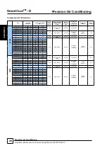
Refrigerant Pipe Sizing Guide
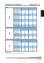
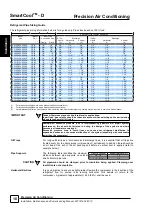
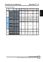
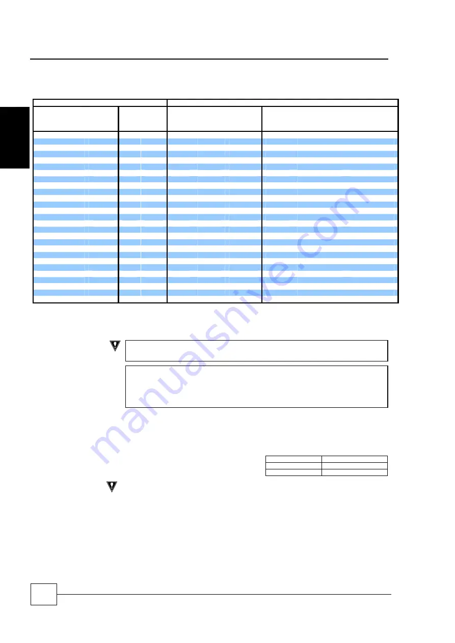
The refrigerant pipe sizing information below is for a guide only. Pipe sizes based on 100% load.
Equivalent Pipe Lengths with R410A
Indoor
Unit
Outdoor
Unit
Indoor Unit
Connection Size
0-15m
Discharge
15-40m
Discharge
Liquid
Disch
Liquid
(3)
Horizontal
(1)
Vertical
(2)
Liquid
(3)
Horizontal
(1)
Vertical
(2)
SC19D055-X2X2-0
CR50
1/2"
7/8"
5/8"
7/8"
3/4"
5/8"
7/8"
7/8"
SC19D070-X2X2-0
CR65
5/8"
7/8"
5/8"
7/8"
7/8"
5/8"
7/8"
7/8"
SC19D080-X2X2-0
CR65
5/8"
7/8"
5/8"
7/8"
7/8"
3/4"
7/8"
7/8"
SC25D080-X2X2-0
CR65
5/8"
7/8"
5/8"
7/8"
7/8"
3/4"
7/8"
7/8"
SC25D090-X2X2-0
CR65
7/8"
1 1/8"
5/8"
7/8"
7/8"
3/4"
7/8"
7/8"
SC25D100-X2X2-0
CR80
7/8"
1 1/8"
3/4"
1 1/8"
1 1/8"
3/4"
1 1/8"
1 1/8"
SC31D100-X2X2-0
CR80
7/8"
1 1/8"
3/4"
1 1/8"
1 1/8"
3/4"
1 1/8"
1 1/8"
SC31D120-X2X2-0
CR105
7/8"
1 1/8"
3/4"
1 1/8"
1 1/8"
3/4"
1 1/8"
1 1/8"
SC31D130-X2X2-0
CR105
7/8"
1 1/8"
3/4"
1 1/8"
1 1/8"
7/8"
1 1/8"
1 1/8"
SC19D033-X2C0-0
CR50
1/2"
7/8"
5/8"
7/8"
3/4"
5/8"
7/8"
7/8"
SC19D038-X2C0-0
CR65
5/8"
7/8"
5/8"
7/8"
7/8"
5/8"
7/8"
7/8"
SC19D045-X2C0-0
CR65
5/8"
7/8"
5/8"
7/8"
7/8"
3/4"
7/8"
7/8"
SC19D064-X2C0-0
CR105
5/8"
7/8"
3/4”
1 1/8”
1 1/8”
7/8”
1 3/8”
1 1/8”
SC19D070-X2C0-0
CR105
7/8"
1 1/8"
3/4”
1 1/8”
1 1/8”
7/8”
1 3/8”
1 1/8”
SC19D076-X2C0-0
CR105
7/8"
1 1/8"
3/4”
1 1/8”
1 1/8”
7/8”
1 3/8”
1 1/8”
SC25D045-X2C0-0
CR65
7/8"
1 1/8"
5/8"
7/8"
7/8"
3/4"
7/8"
7/8"
SC25D050-X2C0-0
CR65
7/8"
1 1/8"
5/8"
7/8"
7/8"
3/4"
7/8"
7/8"
SC25D055-X2C0-0
CR80
7/8"
1 1/8"
3/4"
1 1/8"
1 1/8"
3/4"
1 1/8"
1 1/8"
SC25D067-X2C0-0
CR105
7/8"
1 3/8"
3/4”
1 1/8”
1 1/8”
7/8”
1 3/8”
1 1/8”
SC25D073-X2C0-0
CR105
7/8"
1 3/8"
3/4”
1 1/8”
1 1/8”
7/8”
1 3/8”
1 1/8”
SC25D080-X2C0-0
CR105
7/8"
1 3/8"
3/4”
1 1/8”
1 1/8”
7/8”
1 3/8”
1 1/8”
SC31D055-X2C0-0
CR80
7/8"
1 3/8"
3/4"
1 1/8"
1 1/8"
3/4"
1 1/8"
1 1/8"
SC31D065-X2C0-0
CR105
7/8"
1 3/8"
3/4"
1 1/8"
1 1/8"
3/4"
1 1/8"
1 1/8"
SC31D075-X2C0-0
CR105
7/8"
1 3/8"
3/4"
1 1/8"
1 1/8"
7/8"
1 1/8"
1 1/8"
SC31D077-X2C0-0
CR105
7/8"
1 3/8"
3/4”
1 1/8”
1 1/8”
7/8”
1 3/8”
1 1/8”
SC31D080-X2C0-0
CR105
7/8"
1 3/8"
3/4”
1 1/8”
1 1/8”
7/8”
1 3/8”
1 1/8”
SC31D083-X2C0-0
CR105
7/8"
1 3/8"
3/4”
1 1/8”
1 1/8”
7/8”
1 3/8”
1 1/8”
(1)
For interconnecting pipework with a predominantly horizontal layout.
(2)
For interconnecting pipework with a predominantly vertical layout.
(3)
Careful pipework selection must be done if the liquid line rises. Additional system sub cooling may be required to overcome friction losses.
IMPORTANT
Tandem Compressor and suction throttle valve applications:
In part load, gas velocity should be taken into account when selecting and commissioning
pipework to ensure full oil return.
REMEMBER excessive pressure loss in interconnecting pipework will impair system
performance; this should be factored in during the design of the system and where
necessary oil separators employed.
Excessive pressure drop in liquid lines can cause poor refrigerant distribution to
expansion devices and can cause malfunction of the system (especially with condensers
lower than the evaporator)
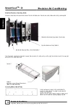
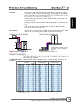
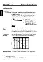
Oil Traps
For long vertical rises in both liquid and discharge lines, it is essential that oil traps are
located every 4m to ensure proper oil movement / entrapment. In addition there should be
an oil trap at the exit of the air handling unit before a vertical riser is applied (refer to
example below).
Pipe Supports
The following table identifies the maximum
distance between pipe supports on vertical
and horizontal pipe runs.
Pipe O/D (inches)
Support distance (m)
3/8 - 7/8
1.0
1 1/8 - 2 1/8
2.0
CAUTION
All pipework should be clamped prior to insulation being applied. Clamping over
insulation is not acceptable.
Horizontal Sections
It is good practice to ensure a slight gradient toward the compressor in the direction of the
refrigerant flow for suction lines running horizontal. This assists oil return to the
compressor. A gradient of approximately 1:200 (0.5%) shall be used.
Ins
ta
ll
a
ti
on

