35
Control System Instruction
Power Cable Connection Diagram
N
R
T N
S
T N
R S
L2
L3
N
S
R
T
P E
14#
Slave unit
B reak er with a
current leakage
protector
B rea ker with a
current leakag e
protector
B reak er with a
current leak age
protector
380-41 5V/3N~/50H z
0#
L1
N
R
T N
S
T N
R S
L2
L3
N
S
R
T
P E
B reak er with a
current leakage
protector
B rea ker with a
current leakag e
protector
B reak er with a
current leak age
protector
380-41 5V/3N~/50H z
L1
N
R
T N
S
T N
R S
L2
L3
N
S
R
T
P E
B reak er with a
current leakage
protector
B rea ker with a
current leakag e
protector
B reak er with a
current leak age
protector
380-41 5V/3N~/50H z
L1
N
R
T N
S
T N
R S
L2
L3
N
S
R
T
P E
B reak er with a
current leakage
protector
B rea ker with a
current leakag e
protector
B reak er with a
current leak age
protector
380-41 5V/3N~/50H z
L1
N
R
T N
S
T N
R S
L2
L3
N
S
R
T
P E
Master unit
B reak er with a
current leakage
protector
B rea ker with a
current leakag e
protector
B reak er with a
current leak age
protector
380-41 5V/3N~/50H z
Slave unit
L1
■
The dimension of power cable connection refer to electical parameters.
■
All wires must be securely connected.
■
Wires must not contact the refrigerating pipes or moving parts of the compressor and the fan.
PCB Instruction
380-415V/3N/50HZ
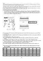
■ Connection illustration for pumps and other parts
A5MAC210/230D
KM7: Water pump congtrol contactor.
KM8: Water system heater control contactor.
A5MAC340/450D(R)
KM11: Water pump congtrol contactor
KM12:
Water system heater control contactor
Summary of Contents for A5MAC 210D
Page 1: ...Technical Manual AIR COOLED MODULAR CHILLER A5MAC 210D A5MAC 230D A5MAC 340D A5MAC 450D...
Page 14: ...14 Wiring Diagrams MODEL A5MAC210 230D...
Page 15: ...16 1 4 5 3 2 7 8 6 1 4 5 3 2 7 8 6 A5MAC340DR...
Page 16: ...17 1 4 5 3 2 7 8 6 1 4 5 3 2 7 8 6 A5MAC450D...
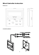
Page 36: ...38 Wired Controller Instruction Dimensions Controller Installation...


