control). Size the pump head based on the system water flow-rate and pressure.
26
■
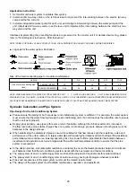
Installation illustration for multiple unit and variable flow rate system:
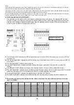
1. By default, the unit is set as constant water flow-rate system. SW1.6 on PCB board indicates the water system,
OFF is for constant flow-rate system, ON is for variable flow-rate system. Please refer to “Setting up address
using DIP switch” for setting.
2. Install one electric two-way valve at the outlet of each slave unit to implement the inter-locking with the unit.
3. Install one electric two-way valve in each piece of terminal equipment to implement the inter-locking between the
valve and the terminal. (Generally, relevant interface is preserved on the terminal fan coil unit. For details about
wiring, please refer to the instruction for fan coil unit.)
4. At least one variable-frequency water pump is required to serve as the chilled water pump for the water system
(it is recommended to use variable-frequency water pumps only to simplify the control and increase the precision
Install a variable-speed water
5.
Install a differential pressure, ΔP sensor at both the return and supply of the chilled water system.
Check the pressure different for both the supply and return. The transmitted signal generated due to the
differential pressure should change the speed of the variable frequency water pump and thus the flow rate
of the chilled water system.
DN20
Full
Drain
Refill
DN20
Exhaust
P
Differential pressure sersor
Differential pressure bypass valve
VFD
VFD Pump
Electronic 2-way valve
Electronic 2-way valve
VFD control cabinet
F
a
n
co
il
F
a
n
co
il
F
a
n
co
il
F
a
n
co
il
F
a
n
co
il
F
a
n
co
il
F
a
n
co
il
pump and transducer to implement variable frequency.
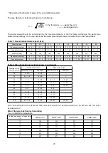
5.1 Requirement for minimum water flow-rate adjustment: the variable frequency adjustment range of water pump
is 50Hz ~ 35 Hz, the selected minimum water flow-rate for adjustment shall not be lower than 70% of the total
designed water flow-rate (ensure that the water flow of a single unit is no less than 70% of the rated water
flow). The more fan coil units is used for a particular system, the smaller the minimum flow-rate ratio could be
use. Thus, configure and troubleshoot based on actual condition.
5.2 Requirement for flow rate changes: the rate of which the flow rate is changed cannot be too frequent. Other
wise, the stability of outlet temperature and terminal regulating valve will be affected. It is recommended to fix
the flow rate changes to 2% ~ 30% per minute, the specific value varies depends on the model, control, and
cycle time of water in the system. The optimum rate for flow rate changes shall be determined on site after
debugging, and the adjustment rate of 10% per minute could be use as the initial value for system debugging.
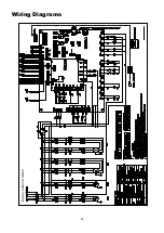
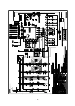
6. In the wiring diagram that are shown previously, components such as contactors and terminal block can be seen.
It was meant for constant flow rate system, a variable flow rate system will require frequency converter, DDC,
differential pressure sensors and other components that might be needed in a variable flow rate system. Core
components that make a variable flow rate differ than the constant flow rate system are as follow:
Summary of Contents for A5MAC 210D
Page 1: ...Technical Manual AIR COOLED MODULAR CHILLER A5MAC 210D A5MAC 230D A5MAC 340D A5MAC 450D...
Page 14: ...14 Wiring Diagrams MODEL A5MAC210 230D...
Page 15: ...16 1 4 5 3 2 7 8 6 1 4 5 3 2 7 8 6 A5MAC340DR...
Page 16: ...17 1 4 5 3 2 7 8 6 1 4 5 3 2 7 8 6 A5MAC450D...
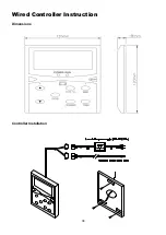
Page 36: ...38 Wired Controller Instruction Dimensions Controller Installation...


