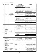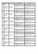
36
NOTE:
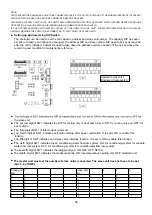
PARTS WITHIN THE DASHED BOX ARE TO BE CONNECTED ONSITE. THE OUTPUT VOLTAGE OF THE MODULE INTERFACE IS 220-240 V.
PARTS WITHIN THE REAL-LINE BOX ARE CONNECTED BEFORE DELIVERY.
2WV:WATER SYSTEM 2-WAY VALVE, OV-PUMP: PUMP OVERLAOD PROTECTION, OV-WHEAT: WATER SYSTEM HEATER OVERLOAD
PROTECTION, EN-SAVE: 2-WAY VALVE INTERLOCKING OR REMOTE CONTROL SWITCH.
IF THE
SYSTEM OPERATES WITH
WATER
SYSTEM OF "ONE PUMP FOR ONE UNIT". FOR WATER PUMP CONTROLS FOR SLAVE
■
Setting up Address Using DIP Switch
The controller can be used to set the unit capacity, address and slave unit number. The capacity DIP has been
set prior of delivery and cannot be changed. The address DIP and slave number DIP need to be set as required
after the unit is installed. Customers need to take down the address number. Location of the unit and keep the
record in good condition for maintenance reference.
Upward represents 1
Downward represents 0
■
the slave unit.
■
The second digit of SW1 indicates the DIP for cooling only or heat pump. Set to 'ON' for cooling only and 'OFF' for
heat pumps.
■
The third digit of SW1 of this model is reserved.
■
The fourth digit of SW1 indicates automatic startup after power restoration. It is set to ON to enable this
The fifth digit of SW1 indicates end 2-way valve interlock function. It is set to ON to enable this function.
■
■
The sixth digit of SW1 indicates the air conditioning water flow rate system. ON: Air conditioning system for variable
water flow rate system; OFF: Air conditioning system for constant water flow rate system.
■
The seventh digit of SW1 indicates the refrigerant type. ON: R22; OFF: R410A.
■
The eighth digit of SW1 indicates the model variations. ON: low-temperature heating unit; OFF: standard unit.
■
The master unit must set the number of slave unit(s) connected. The slave unit does not have to be set
(bits 1~4 of SW2):
Slave unit
Qty.
1
2
3
4
Slave unit
Qty.
1
2
3
4
0
0
0
0
0
8
1
0
0
0
1
0
0
0
1
9
1
0
0
1
2
0
0
1
0
10
1
0
1
0
3
0
0
1
1
11
1
0
1
1
4
0
1
0
0
12
1
1
0
0
5
0
1
0
1
13
1
1
0
1
6
0
1
1
0
14
1
1
1
0
7
0
1
1
1
15
1
1
1
1
UNIT WILL REQUIRE THE PUMP TO BE CONNECTED TO "2WV" POINT OF SLAVE UNITS.
function.
Summary of Contents for A5MAC 210D
Page 1: ...Technical Manual AIR COOLED MODULAR CHILLER A5MAC 210D A5MAC 230D A5MAC 340D A5MAC 450D...
Page 14: ...14 Wiring Diagrams MODEL A5MAC210 230D...
Page 15: ...16 1 4 5 3 2 7 8 6 1 4 5 3 2 7 8 6 A5MAC340DR...
Page 16: ...17 1 4 5 3 2 7 8 6 1 4 5 3 2 7 8 6 A5MAC450D...
Page 36: ...38 Wired Controller Instruction Dimensions Controller Installation...


