28
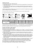
Application instruction:
1. Set master unit water system to variable
fl
ow system.
2. Install electric two-way valve on the terminal side to implement the inter-locking between the electric two-way
valve and the fan coil unit.
3.
unit. Install electric two-way valve on each slave unit to implement the inter-locking between the electronic two-
Install an independent water pump for each unit, and configure interworking between the water pump and the
way valve and the unit.
Interfaces implementing the preceding functions are preserved on the master unit. For details about wiring, please
refer to "Control System Instruction - PCB Instruction".
NOTE: PUMP IS OPTIONAL, PLEASE CONTACT YOUR LOCAL DISTRIBUTOR SHOULD YOU HAVE FURTHER ENQUIRIES.
■
Legends for the water system illustration:
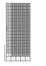
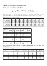
Size of the main connecting pipe for modular combinations:
Unit Qty.
1
2~3
4~5
6~10
11~16
Size of main connecting pipe
(inch)
A5MAC210/230D
≥2
≥3
≥4
≥5
≥6
A5MAC340/450D(R)
≥2.5
≥4
≥5
≥7
≥9
NOTE: WHEN CLEANING THE WATER SYSTEM, PLEASE SHUT
① ②
GATE VALVE AND OPEN
③
GATE VALVE MARKED IN THE
DIAGRAM OF ALL THE UNITS, IN ORDER TO BYPASS THE UNITS, SO THE IMPURITIES CAN BE PREVENTED FROM ENTERING THE
PLATE HEAT EXCHANGER AND THE EFFICIENCY AND SERVICE LIFE OF PLATE HEAT EXCHANGER CAN NOT BE AFFECTED.
Hydraulic Calculation and Pipe System
Pipe Design for the Air-Conditioning System
■
Please ensure the piping for both condenser and chilled water system is sufficient. For example, the water system
must ensure that the water flowing through the air conditioning unit or fan coil reaches the rated flow rate to ensure
that the unit work properly
Deploy pipes properly, use pipes with reverse return if possible. Although the initial investment is increased,
the flow rate will be more stable. If pipes have no reverse return design, pressure between branch pipes must be
balanced in the design process.
■
■
When determining the diameters of pipes, ensure it is suitable for that flow rate as such the resistance, noise and
performance of the unit is optimum. A larger water pipe will require higher initial investment but lower flow resistance
and smaller pump could be use, lowering operating cost. It is crucial to find a pipe diameter that balance between
investment and operation cost. Avoid a large water flow with small temperature variation to ensure that the pipe
system is economical.
■
In the design process, calculate water resistance accurately to ensure that water pressures between circuits are
well balanced and that the air conditioning system works with the best water and thermal conditions.
■
The pipe system of an air conditioning system must meet the adjustment requirements for partial workload.
■
The pipe system of an air conditioning system should use energy saving technologies whenever possible.
■
Pipes and accessories of the pipe system must meet the related requirements
■
The design of the pipe system must facilitate maintenance, operation, and adjustment.
Summary of Contents for A5MAC 210D
Page 1: ...Technical Manual AIR COOLED MODULAR CHILLER A5MAC 210D A5MAC 230D A5MAC 340D A5MAC 450D...
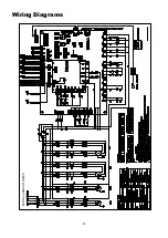
Page 14: ...14 Wiring Diagrams MODEL A5MAC210 230D...
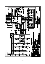
Page 15: ...16 1 4 5 3 2 7 8 6 1 4 5 3 2 7 8 6 A5MAC340DR...
Page 16: ...17 1 4 5 3 2 7 8 6 1 4 5 3 2 7 8 6 A5MAC450D...
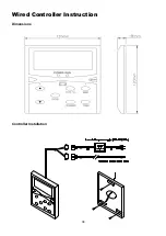
Page 36: ...38 Wired Controller Instruction Dimensions Controller Installation...

