


-
-
35
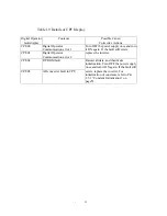
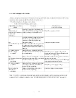
1.7.3 Corrective Action for Motor Faults
Table 1.11 shows the check points and corrective actions of motor faults.
Table 1.11 Motor Faults and Corrective Actions
Fault
Check point
Corrective Action
Power supply voltage is applied to power
supply terminals R, S, T.
(Check that charge lamp is ON.)
• Turn ON the power supply.
• Turn OFF the power supply and then
ON again.
• Check power supply voltage.
• Check that terminal screws are tight.
Voltage is output to output terminals U, V,
W (Use rectifier type voltmeter.)
• Turn OFF the power supply and then
ON again.
Load is excessively large. (Motor is
locked.)
Reduce the load. (Release the lock.)
Fault is displayed.
Check according to Par. 1.7.1.
FWD or REV run command is entered.
Correct the wiring.
Frequency setting voltage is entered.
˙
Correct the wiring.
˙
Check frequency setting Voltage.
Motor does not
rotate.
Operation (method selection) mode
setting is proper.
Check the operation method Selection
mode [constant Pn-01] by using the
digital operator.
Wiring of output terminals U, V, W is
correct.
Match them to the phase order of motor
U, V, W.
Motor rotating
direction is
reversed.
Wiring of FWD and REV run signals is
correct.
Correct the wiring.


