


-
-
32
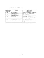
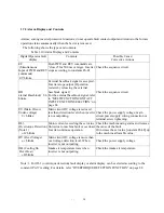
Table 1.8 Fault Display and Contents (Cont’d)
Digital Operator
fault display
Contents Possible
Cause/
Corrective Actions
OL1
(Motor Overload)
Motor overload protection operates
because of electronic thermal
overload.
Correct load size, operation pattern or V/f set
value [constant Pn-02~08].
Set the rated current value described in the
motor nameplate to constant Pn-19.
OL2
(Inverter Overload)
Inverter overload protection
operates because of electronic
thermal overload.
Correct load size, operation pattern or V/f set
value [constant Pn-02~08].
Recheck the inverter capacity.
OL3
(Overtorque
Detection)
Motor current exceeding set value
is applied because of machine fault
or overload.
Check the machine using status and remove
the cause. Or increase the set value up to the
machine allowable value [constant Pn-38].
EF4.5 (Note 2)
(External Fault)
Inverter accepts external fault
input from external circuit.
Check the external circuitry (sequence).
CPF (Note 3)
(Control Function
Fault)
Inverter control functions are
broken down
Turn OFF the power supply once and then
turns it ON again. Or initialize the control
constant by using the digital operator.
If the fault still exists, replace the inverter.
Digital display is
extinguished.
˙
Main circuit fuse is blown. (For
440V class only)
• Control power supply fault
• Hardware fault
Replace the inverter.
Note: 1. For OL3 ( overtorque detection) fault display or alarm display can be selected according to the
constant (Pn-37) setting. For details, refer to “OVERTORQUE DETECTION FUNCTION” on
page 99.
2. EF4 shows external fault input from multifunction contact input terminal 4,and EF5 from terminal 5.
3. For details of CPF (control function faults) refer to Table 1.9. “Details of CPF Display.


