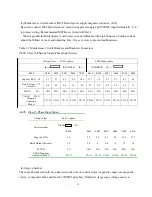


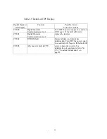


Inverter
Status
LED Display
DSI (RED.)
Display Contents
Remarks
Operation ready (during STOP)
Normal
During normal RUN
Alarm
Power supply voltage reduction, external
BB inputting. Etc. in STOP status
Automatic recovery by
protective operation
release
Inverter external fault (EF is input).
Overload protection such as inverter
overload (OL.), fin overheat, etc.
Can be reset by removing
the factor.
(Hardware fault if not
recovered)
Voltage protection such as over voltage
(OV) under voltage (UV)
Protective operation
Over current protection (OC)
Digital hardware memory fault (CPF)
Cannot be reset
(replace the inverter)
(Note 1)
Inverter fault
●
Hardware fault such as control power supply
fault, CPU runaway, etc.
Cannot be reset.
(Replace the inverter).
●
: LED light off, : LED blink, :LED light
Note 1. By initializing control constants using the digital operator, errors may be released. For details of
constant initialization, refer to “DISPLAY OF OPERATOR” on page 67.
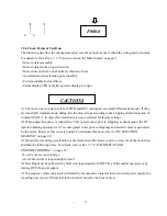
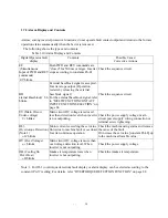
1.5.5 Digital Operator Display
When the inverter power supply is turned ON for the first time, the digital operator displays as shown
below. If an alarm is displayed, refer to Par 1.7 “FAULT DISPLAY AND TROUBLESHOOTING” on
page 26 to remove the factor.
1. 2. 3.
1. Drive mode display (DRV): Lights.
2. Rotating direction display (FWD): Lights
(REV): Extinguished
3. EXT mode display (EXT RUN, CMD):
Extinguished.
4 .During RUN display (RUN):
5. During STOP display (STOP): Lights.
6. 7-segment LED display (5digits):
Output frequency reference set value


