


-
-
34
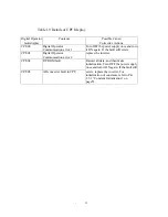
1.7.2 Alarm Display and Contents
Alarms, among inverter protective functions, do not operate fault contact output and returns to the former
operation status automatically when the factor is removed.
The following shows the types and contents.
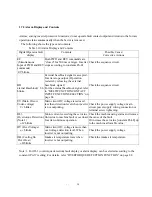
Table 1.10 Alarm Display and Contents
Digital Operator fault
display
Contents Possible
Cause/
Corrective Actions
EF
(Simultaneous
Input of FWD and REV
commands)
EF
blinks.
Both FWD and REV commands are
“closed” for 500 ms or larger. Inverter
stops according to constants Pn-01.
Check the sequence circuit.
BB
External Baseblock)
bb
blinks.
External baseblock signal is accepted.
Inverter stops output. (Operation
restarts by releasing the external
baseblock signal.)
For the external baseblock signal, refer
to “MULTIFUNCTION CONTACT
INPUT FUNCTION SELECTION” on
page 84.
Check the sequence circuit
UV (Main Circuit
Under-voltage)
Uv
blinks.
Main circuit DC voltage is reduced
less than detection level when inverter
is not outputting.
Check the power supply voltage, main
circuit power supply wiring connection or
terminal screw tightening.
OL3
(Overtorque Detection)
(Note 1)
oL3
blinks
Motor current exceeding the set value
flows due to machine fault or overload.
Inverter continues operation.
Check the machine using status and remove
the cause of the fault.
Or increase the set value [constant Pn-38] up
to the machine allowable value.
OV (Over Voltage)
ov
blinks
Main circuit DC voltage is more than
overvoltage detection level. When
inverter is not outputting.
Check the power supply voltage
OH (Cooling fin
Over Heat)
oH
blinks
Intake air temperature rises when
inverter is not outputting.
Check the intake air temperature.
Note: 1. For OL3 (overtorque detection) fault display or alarm display can be selected according to the
constant (Pn-37) setting .For details, refer “OVERTORQUE DETECTION FUNCTION” on page 88.


