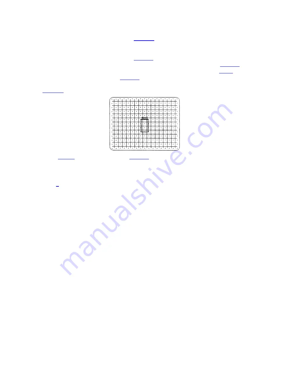
OPERATION
To change the convergence color, press
COLOR
.
Each press of the Color key changes
the color as shown.
To move to another control point, press
ENTER
.
The caption above the box changes to
''MOVE''. Use the arrow keys to move to another zone for convergence. Press
ENTER
to
converge the zone. When all zones requiring adjustment are converged, press
EXIT
to
display the Exit dialog box. Press
ENTER
to save the new convergence settings. To go
back to the convergence screen, move the cursor bar to ''Continue Adjust'', then press
ENTER.
To discard your changes select ''No Save''
Note:
CONV
may be used instead of
ENTER
to alternate between converge and
move
functions, if preferred.
ACON Automatic
Convergence
>
Press
4
from the Convergence Menu to display the ACON Auto-convergence Menu. The
menu displays five ACON options for selection and shows the most recent ACON status
message (if there is one).
Note: The ACON Auto-convergence Menu is
available only
if
the projector includes the
optional ACON feature.
Before using ACON for the first time it is important to understand how ACON operates.
ACON consists of two primary components; a Locator Assembly, normally mounted to
the front of the projector, and an ACON Control Board, located inside the projector. The
Locator Assembly includes a photosensor, which, via two stepper motors, can monitor
any point on the display screen. The ACON Control Board controls the viewing position
of the photosensor. During automatic convergence, small red, green, and blue targets are
displayed for viewing by the photosensor. Data from the photosensor is analyzed and
convergence adjustments are made accordingly. The lens of the Locator Assembly can be
observed to move about as each convergence zone is analyzed and adjusted. No user
intervention is required.
WARNING: IN RARE INSTANCES, FLASHING LIGHTS CAN TRIGGER AN
EPILEPTIC SEIZURE. DURING ACON OPERATION PERSONS WITH EPILEPSY
SHOULD NOT WATCH THE SCREEN.
3-28
Summary of Contents for Model 9
Page 1: ......
Page 44: ...INSTALLATION SETUP Figure 2 29 ACON Installation Examples 2 38...
Page 104: ...Physical Dimensions 5 5...
Page 105: ...5 6...
Page 113: ...A p p e n d i x B B 1...
Page 114: ...B 2...
Page 115: ...C 1...
Page 116: ...C 2...
Page 117: ...D 1...
Page 118: ...D 2...
Page 119: ...E 1...
Page 120: ...F 1...
Page 121: ...F 2...
Page 122: ...F 3...
Page 123: ...F 4...
Page 124: ...F 5...
Page 125: ...F 6...
Page 126: ...F 7...
Page 127: ...F 8...
Page 128: ...F 9...
Page 129: ...F 10...
Page 130: ...G 1...
Page 131: ...Index 1...
Page 132: ...Index 2...


