INSTALLATION & SETUP
Step 2
>
Case Removal
Locate the four screws around the base perimeter of the back portion of the fiberglass
case, and the four screws on the base perimeter of the front portion of the fiberglass case.
Unscrew these screws, and then gently slide the front cone off, pulling away from the
center, straight out. You will now see two new screws located on top of the frame. These
screws are the last screws holding the rear fiberglass portion to the projector. Remove
these screws and gently pull the case off the backside, straight out.
Case Placement
The placement of the case back on the projector is just as simple as its removal. Just be
sure to put the rear section of the case on the projector before the front portion.
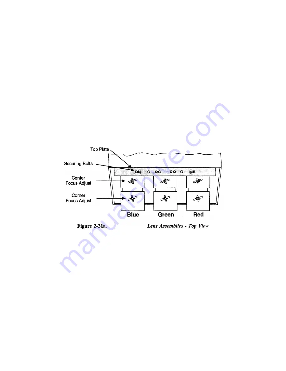
Examine the lenses and hardware as shown in Figure 2-21a (or, for the model 8, see
Figure 2-21b).
Each lens consists of a rear section and a front section. The rear section
sets the optical focus at the center of the image and is secured to the lens body by a wing
nut at the top rear of the lens assembly. The front section sets the focus at the corners and
is secured to the rear section by a wing nut at the top front of the lens assembly.
2-17
Summary of Contents for Model 9
Page 1: ......
Page 44: ...INSTALLATION SETUP Figure 2 29 ACON Installation Examples 2 38...
Page 104: ...Physical Dimensions 5 5...
Page 105: ...5 6...
Page 113: ...A p p e n d i x B B 1...
Page 114: ...B 2...
Page 115: ...C 1...
Page 116: ...C 2...
Page 117: ...D 1...
Page 118: ...D 2...
Page 119: ...E 1...
Page 120: ...F 1...
Page 121: ...F 2...
Page 122: ...F 3...
Page 123: ...F 4...
Page 124: ...F 5...
Page 125: ...F 6...
Page 126: ...F 7...
Page 127: ...F 8...
Page 128: ...F 9...
Page 129: ...F 10...
Page 130: ...G 1...
Page 131: ...Index 1...
Page 132: ...Index 2...


