INSTALLATION & SETUP
the phosphor is spread out, thus reducing the noticeable effects of ''phosphor burn''. The
ISM accepts RGB
video signals from a variety of signal types:
sync-on-green, composite
(not composite video) and
separate H
&
V.
Inputs are by way of standard BNC
type
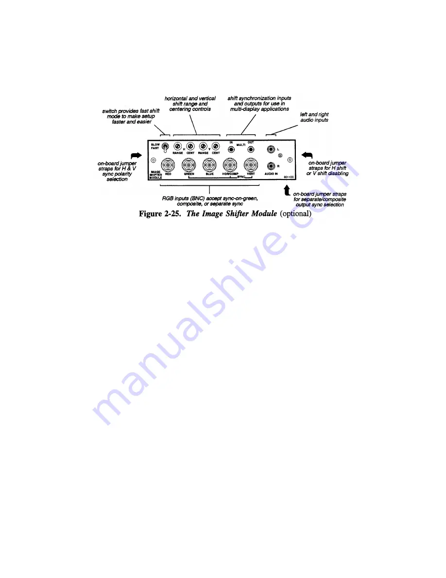
connections. The ISM includes a number of features. See Figure 2-25.
About Image Shifting >
To provide image shifting, the ISM takes the input and
slowly shifts the phase of its horizontal and vertical sync signals with respect to incoming
sync. Since the incoming RGB
video and incoming sync are generated at their source in
phase with each other, regenerating the sync with a shifting phase relationship shifts the
RGB
video on the display device, which is locked to the output horizontal and vertical
sync of the ISM.
Hook-up & Connections>
As mentioned, the ISM accepts RGB
video signals with
any one of the following sync types: sync-on-green (3 wire), composite (4 wire) and
separate H & V (5 wire). To connect a source, connect the red, green, and blue outputs to
the RED, GREEN, and BLUE inputs on the interface module. If the source uses sync on
green, no additional cables are required. If the source provides a composite sync output,
connect it to the HOR/COMP input. lf the source provides separate horizontal and
vertical sync outputs, connect the horizontal sync signal to the HOR/COMP
input, and
connect the vertical sync input to the VERT input. Interconnection cables must have
BNC
type connectors. See Figure 2-26 below.
If the source includes pre-amplified
(line level) audio outputs, connect them to the left
and right channel audio inputs (RCA type phono connections required). Audio outputs
from the built-in interface should then be connected to external audio amplification
equipment for sound output. When the ISM input is selected, the audio inputs to the ISM
are routed to the audio outputs on the projector. This functionality is called ''audio
follows video''.
2-33
Summary of Contents for Model 9
Page 1: ......
Page 44: ...INSTALLATION SETUP Figure 2 29 ACON Installation Examples 2 38...
Page 104: ...Physical Dimensions 5 5...
Page 105: ...5 6...
Page 113: ...A p p e n d i x B B 1...
Page 114: ...B 2...
Page 115: ...C 1...
Page 116: ...C 2...
Page 117: ...D 1...
Page 118: ...D 2...
Page 119: ...E 1...
Page 120: ...F 1...
Page 121: ...F 2...
Page 122: ...F 3...
Page 123: ...F 4...
Page 124: ...F 5...
Page 125: ...F 6...
Page 126: ...F 7...
Page 127: ...F 8...
Page 128: ...F 9...
Page 129: ...F 10...
Page 130: ...G 1...
Page 131: ...Index 1...
Page 132: ...Index 2...


