INSTALLATION & SETUP
If using the projector with a signal switcher, connect an RS-232 serial communication
cable between the switcher and the projector serial port labeled ''SWITCHER''. lf the
projector is to be controlled by a computer or controller which has an RS-232 serial port,
connect an RS-232 serial cable between the computer and the projector serial port labeled
''IN''
.
After the connection is made, set the serial port baud rate as described in the
Projector Setup entry in section 3.7,
Utilities.
Notes: 1) All serial connections require a 9 pin D connector at the projector end. Refer to
Appendix D for cable wiring requirements. 2) For computer/controller control, PC
software is required. 3) The RS232 serial port labeled ''OUT'' is provided for
projector
networking applications.
2.8 Optical
Alignment
Optical alignment is required when the throw distance changes or the projector cannot be
focused using the focus controls. The projector is optically aligned at the factory at a
fixed screen size and a fixed projector-to-screen distance. See Appendices F and G for
the specific details needed for your projector model and lens. If the throw distance has
changed since the last setup, proceed as follows:
Notes: 1) The projector must be warmed up for at least 45 minutes prior to
performing
optical alignment. 2) Optical alignment is both a mechanical and
electrical adjustment.
Electrical adjustments are stored in the current setup
memory. After alignment is
complete, setup memories which
were
previously
set up (if any) must be set up again.
Memory setup is explained in
section 2.10. 3) Factory alignment is performed using the
internal crosshatch
with a 61.8 kHz
signal applied.
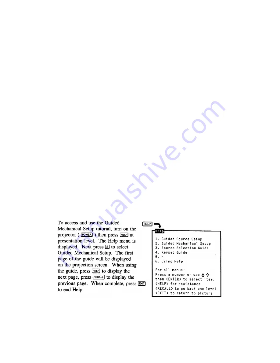
It is recommended that optical alignment be performed using the projector's Guided
Mechanical Setup tutorial. This tutorial displays step-by-step instructions during the
alignment. The instructions in this section require use of the Guided Mechanical Setup
tutorial.
Step 1
>
If you have not already done so, calculate the throw distance and set the projector
position as explained in section 2.4,
Mounting.
Turn power off before moving the
projector.
2-16
Summary of Contents for Model 9
Page 1: ......
Page 44: ...INSTALLATION SETUP Figure 2 29 ACON Installation Examples 2 38...
Page 104: ...Physical Dimensions 5 5...
Page 105: ...5 6...
Page 113: ...A p p e n d i x B B 1...
Page 114: ...B 2...
Page 115: ...C 1...
Page 116: ...C 2...
Page 117: ...D 1...
Page 118: ...D 2...
Page 119: ...E 1...
Page 120: ...F 1...
Page 121: ...F 2...
Page 122: ...F 3...
Page 123: ...F 4...
Page 124: ...F 5...
Page 125: ...F 6...
Page 126: ...F 7...
Page 127: ...F 8...
Page 128: ...F 9...
Page 129: ...F 10...
Page 130: ...G 1...
Page 131: ...Index 1...
Page 132: ...Index 2...


