INSTALLATION & SETUP
Note:
on all models, it may be necessary to readjust the lens' rear wing nut to keep the
center defocused.
Step 33 >
Rotate the blue lens using the rear wing nut until the picture is focused in the
center. Tighten the rear wing nut. If necessary, loosen the front wing nut, rotate the front
lens barrel to readjust the focus in the corners, then re-tighten the wing nut. See Step 15.
Step 34 >
For the Model 8 & 9, optical alignment is now complete. Install the front top
cover. Proceed to set up each source by following the source setup procedure in section
2.9,
Source Setup.
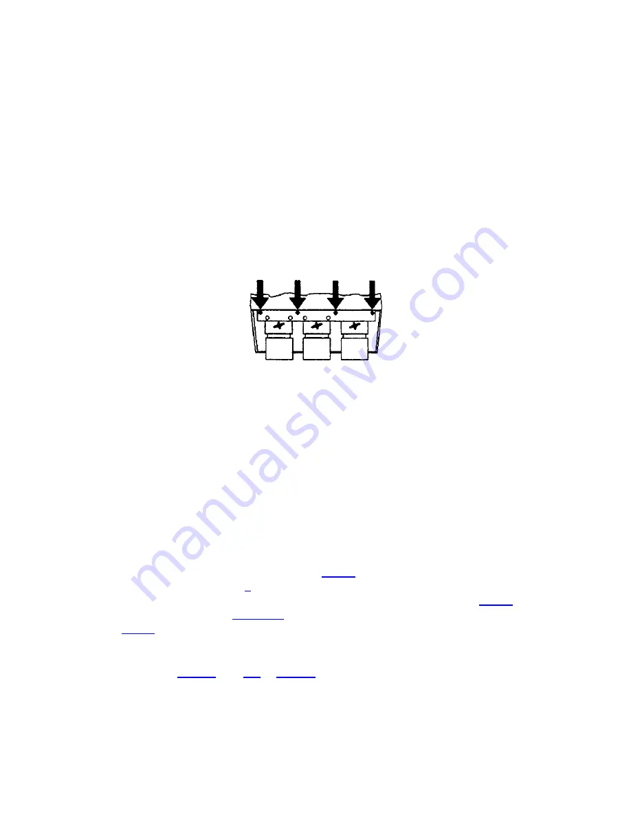
On the Model 8, tighten the bolts labeled
''A''.
Optical alignment is now complete. Install
the front top cover. Proceed to set up each source by following the source setup
procedure in section 2.9,
Source Setup.
B G R
2.9 Source Setup
This section gives step-by-step instructions for quick setup of the projector for a selected
external source. For a complete setup, repeat these steps as required for each source
connected to the projector.
Before starting, ensure that the projector is optically and mechanically aligned. If optical
alignment is required, follow the setup instructions in section 2.8,
Optical Alignment.
Select the source to be set up using the Source command and make sure it is visible on
the projection screen.
To make setup easier, it is recommended that you use the projector's Guided Source
Setup tutorial. It provides source setup instructions on screen to guide you through the
adjustments. To access the tutorial, first press
HELP
at presentation level. The Help
menu is displayed. Next press
1
to select Guided Source Setup. The first page of the
guide will be displayed on the projection screen. When using the guide, press
HELP
to
display the next page, press
RECALL
to display the previous page. When complete,
press
EXIT.
Step
1
>
Press
BRITE
then
UP
or
DOWN
to increase or decrease the brightness
setting until black areas in the image just disappear.
2-24
Summary of Contents for Model 9
Page 1: ......
Page 44: ...INSTALLATION SETUP Figure 2 29 ACON Installation Examples 2 38...
Page 104: ...Physical Dimensions 5 5...
Page 105: ...5 6...
Page 113: ...A p p e n d i x B B 1...
Page 114: ...B 2...
Page 115: ...C 1...
Page 116: ...C 2...
Page 117: ...D 1...
Page 118: ...D 2...
Page 119: ...E 1...
Page 120: ...F 1...
Page 121: ...F 2...
Page 122: ...F 3...
Page 123: ...F 4...
Page 124: ...F 5...
Page 125: ...F 6...
Page 126: ...F 7...
Page 127: ...F 8...
Page 128: ...F 9...
Page 129: ...F 10...
Page 130: ...G 1...
Page 131: ...Index 1...
Page 132: ...Index 2...


