39
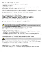
Parameter
Settable
value limits
Default
16 kW
methane
Default
16 kW
LPG
Default
24 kW
methane
Default
24 kW
LPG
Default
28 kW
methane
Default
28 kW
LPG
Default
32 kW
methane
Default
32 kW
LPG
P2 - TSP02
Gas type
0 - 1
0
1
0
1
0
1
0
1
P4 - TSP04
Heating curves
0 ÷ 90
30
30
30
30
30
30
30
30
P8 - TSP08
Upper limit of maximum heating power
P10 ÷ 100%
57
48
75
83
83
83
82
89
P9 - TSP09
DHW maximum power upper limit
P10 ÷ 100%
72
65
100
100
100
100
100
100
P15 - TSP15
Machine type and default data table
0 ÷ 3
3
3
0
0
1
1
2
2
P31 - TSP31
Fan speed at burner ignition power and
propagation (P31x25 [rpm])
80 ÷ 160
140
128
140
128
140
128
140
128
P32 - TSP32
Fan speed at maximum burner power
(DHW) ( 2000 [rpm])
Da TSP33÷
255
170
178
170
178
181
148
170
158
P33 - TSP33
Fan speed at minimum burner power (DHW
and heating) (P33x25 [rpm])
30 ÷ 60
36
36
36
36
36
36
44
36
Table 24 - Limits that can be set for the TSP parameters and default values according to the type of boiler (TSP15)
3.2.14.
Installation of the external probe (optional) and sliding temperature operation
The boiler can be connected to a probe for measuring the outside temperature (optional, not mandatory, supplied by the manufacturer) for
sliding temperature operation.
Use only original external probes supplied by the manufacturer.
If non-original external probes not supplied by the manufacturer are used, correct operation of the external
probe and the boiler is not guaranteed.
The probe for measuring the external temperature must be connected with a double-insulated cable with a minimum section of 0.35
mm
2
.
The external probe must be connected to terminals
E1
and
E2
of the boiler terminal board (fig. 21 and fig. 22).
The cables of the probe for measuring the external temperature must NOT be sheathed together with the power supply cables.
The external probe must be installed on a wall facing NORTH - NORTH EAST, in a position protected from atmospheric agents. Do not
install the external probe in window openings, near ventilation vents or near heat sources.
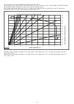
The external temperature probe automatically modifies the heating flow temperature according to:
- external temperature measured;
- selected thermoregulation curve;
- fictitious room temperature set.
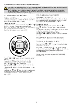
The fictitious room temperature is displayed by pressing the “ ” key (C fig. 1) and subsequently modified by pressing the “ or ” keys
(E or F fig. 1) which, with the external temperature probe installed, loses the function heating water temperature setting (see paragraph 1.10.6)
and the set value can be read on the boiler display. Furthermore, the value of the external temperature detected by the external probe can
also be displayed via the Info menu under the item "In1".
1.TEMPERATURE
REGULATION
FICTIC ENVIRONMENT


