background image

28

3. Instructions for the installer

3.1. Installation rules

This boiler is of category II2H3B / P and must be installed according to the following laws and standards in force which are understood to 

be fully transcribed here:
- Law n° 46 of 05/03/90

- Law n° 186 of 01/03/68

- Legislative Decree No. 192 of 08/19/2005

- Legislative Decree n° 311 of 29/12/2006

- DPR n° 551 of 21/12/1999

- Presidential Decree No. 412 of 08/26/1993

- UNI 7129 standard

- UNI 7131 standard

- UNI 11071 standard

- CEI 64/8 standard

ATTENTION

If several boilers are installed in the same residential unit or in the same room, for a total heat output exceeding 35 kW, the 

systems must be designed and built in compliance with:
- Ministerial Decree 12/04/96 regarding fire prevention;

- DM 01/12/75 and collection R connected with regard to safety.

3.2. Installation

For both installation and maintenance and possible replacement of components, use only original accessories and 

spare parts supplied by the manufacturer.

If original accessories and spare parts are not used, correct operation of the boiler is not guaranteed.

3.2.1. Packing

The boiler is supplied packed in a sturdy cardboard box.

After unpacking the boiler, make sure it is perfectly intact.

The packaging materials are recyclable: therefore convey them to the appropriate collection areas.

Do not leave packaging that can, by their nature, be a source of danger at the mercy of children.

The manufacturer declines all responsibility for damage to people, animals and property resulting from non-compliance 

with the above.

The packaging contains:

-

wall fixing bracket (already mounted on the boiler);

-

bag containing:

a) this manual for installation, use and maintenance of the boiler;

b) the inspection certificate;

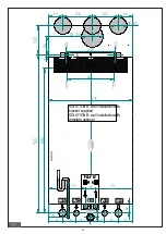
c) the template for fixing the boiler to the wall (fig. 7).

3.2.2. Choice of the place of installation of the boiler

When determining the place to install the boiler, take the following into account:

- the indications contained in paragraph “3.2.6. Air intake / flue gas exhaust system "and its subparagraphs;

- check that the masonry structure is suitable, avoiding fixing on inconsistent partitions;

- avoid mounting the boiler on top of an appliance which, during use, may in some way compromise its proper functioning (kitchens that

give rise to the formation of greasy vapors, washing machines, shower rooms or bathtubs, etc. .).

3.2.3. Positioning of the boiler

Each device is equipped with a special paper template contained in the packaging (fig. 7).

This template allows the preparation of the connection pipes to the heating system, to the domestic water, to the gas network and to the

air intake / flue gas pipes at the time of making the plumbing system and before installing the boiler.

This template, consisting of a sturdy sheet of paper, must be fixed to the wall chosen for the installation of the boiler with the help of a

bubble and shows all the information necessary to drill the holes for fixing the boiler to the wall which is done by means of two screws.

with expansion plugs.

The lower part of the template allows you to mark the exact point where the fittings for connecting the gas supply pipe, the cold water

supply pipe, the hot water outlet, the delivery and the heating return.

The upper part allows you to mark the points where the air intake / flue gas exhaust pipes must be positioned.

Since the temperature of the walls on which the boiler is installed and the external temperature of the coaxial intake 

and exhaust ducts are lower than 60 ° C, it is not necessary to respect minimum distances from flammable walls.

For boilers with split intake and exhaust ducts, in the case of flammable walls and crossings, interpose insulation 

between the wall and the flue gas exhaust pipe.

Summary of Contents for PLAY 24

Page 1: ...1 PLAY 24 28 32 Wall mounted gas condensing boiler for heating and DHW production PLAY 24 28 32 INSTALLATION MANUAL...

Page 2: ...by current legislation 2 according to the provisions of Presidential Decree no 74 of 16 April 2013 the compilation of the system booklet after detecting the combustion parameters must be carried out...

Page 3: ...to repair or direct intervention contact only qualified personnel Any repairs to the product must be carried out with the use of original spare parts Failure to comply with the above may compromise t...

Page 4: ...d only the domestic hot water function will be enabled the system delivery temperature is displayed 5 If you want to activate both the heating function and the domestic hot water function hold down th...

Page 5: ...ller 28 3 1 Installation rules 28 3 2 Installation 28 3 2 1 Packing 28 3 2 2 Choice of the place of installation of the boiler 28 3 2 3 Positioning of the boiler 28 3 2 4 Assembling the boiler 30 3 2...

Page 6: ...iagram 23 fig 7 Installation template 29 fig 8 Support brackets 30 fig 9 Examples of installation 30 fig 10 Intake exhaust with coaxial ducts 35 fig 11 Dimensional dimensions for coaxial ducts 35 fig...

Page 7: ...reasing temperature values and parameters F Key to increase temperature values and parameters To access the interface you need to press a button Activating the interface it enables access to all keys...

Page 8: ...es parameter values and anomalies 4 Indication of the need for manual RESET of the error 5 OT connection present 6 Indication of the unit of measurement of the system pressure 7 Symbol indicating inst...

Page 9: ...time the WINTER modes are enabled in sequence SUMMER and OFF All buttons are active in this phase With the WINTER mode active both functions are active preparation of domestic hot water and preparatio...

Page 10: ...e the value is stored and the display returns to its normal operation Pressing the sanitary button C fig 1 displays the temperature of the heating delivery water Pressing the buttons E fig 1 or F fig...

Page 11: ...n 1 sec n00 1 sec and the value of the relative parameter 5 sec alternate on the screen By briefly pressing the button F fig 1 it is possible to scroll through the various indices When you reach the l...

Page 12: ...9 C 1 In5 Return probe temperature display 9 99 C 1 In6 Real SET heating temperature display Par 13 INST Par 14 INST C 1 In7 Power level display 0 100 1 In8 Flowmeter value display 0 99 l min 0 1 In9...

Page 13: ...MER position Sanitary function active The DHW delivery temperature is displayed and the symbol flashes Boiler selector in WINTER position Sanitary function active The DHW delivery temperature is displ...

Page 14: ...anomaly Ignition failure Intervention of the safety thermostat Parasitic flame Lack of circulation Return NTC probe failure System overtemperature TCH TSP81 Delta T CH Ret TSP82 1 Gas valve modulator...

Page 15: ...ly at start up 2 Problem on the SGV circuit Loss of flame upon ignition for more than 6 consecutive times Software Error Card not configured Generic block Table 4 BOILER STATUS LCD display in case of...

Page 16: ...it the error is released The anomaly signal disappears on the interface and the display turns off 1 8 Automatic elimination of system air By pressing the and keys simultaneously for the cycle time the...

Page 17: ...nd the value that is being set for the heating water temperature is indicated When the heating system requires heat the heating symbol flashes on the display 2 fig 1 and the instantaneous temperature...

Page 18: ...water increasing it when the outside temperature decreases and decreasing it when the outside temperature increases thus improving the environmental comfort and saving fuel The maximum temperatures o...

Page 19: ...f the air intake and or flue gas exhaust systems the boiler is blocked the display shows the flashing code E13 0 E96 intervention of the fumes probe In this case contact an Authorized Service Center o...

Page 20: ...rding to the settings made on the control panel ignoring the settings made on the Re motion Control In this case contact an Authorized Service Center or qualified personnel for maintenance 1 12 Mainte...

Page 21: ...er precedence flow meter User interface Interface with built in LCD for viewing and controlling the boiler operating status OFF UNLOCK WINTER and SUMMER Heating water temperature regulator 20 80 C sta...

Page 22: ...nlet Gas inlet Siphon inspection cap Heating system delivery C R RS RC Bottom view View from above Domestic hot water outlet Return no heating system Drain cock and safety valve drain Filling cock SI...

Page 23: ...sensor 11 Return temperature sensor 12 3 bar safety valve 13 Pressure transducer 14 Deaerator 15 Circulator 16 Drain cock 17 Filling cock 18 Cold water flow meter 19 Secondary plate exchanger 20 Domes...

Page 24: ...pressure of the sanitary circuit bar 6 6 6 Specific flow rate of sanitary water T 30K l min 12 13 3 14 Power supply Voltage Frequency V Hz 230 50 230 50 230 50 Power supply fuse A 3 15 3 15 3 15 Maxi...

Page 25: ...termica in stand by Pstby 0 069 kW elmin 0 054 kW Consumo energetico del bruciatore di accensione Pign 0 kW Auxiliary electricity consumption At full load Part load In stand by mode PSB 0 004 kW Cons...

Page 26: ...tricity consumption At full load Part load In stand by mode PSB 0 004 kW Other elements Stand by heat loss Energy consumption of the ignition burner Annual energy consumption QHE 55 GJ Emission of nit...

Page 27: ...electricity consumption At full load Part load In stand by mode PSB 0 005 kW Other elements Stand by heat loss Energy consumption of the ignition burner Annual energy consumption QHE 62 7 GJ Emission...

Page 28: ...boiler to the wall fig 7 3 2 2 Choice of the place of installation of the boiler When determining the place to install the boiler take the following into account the indications contained in paragrap...

Page 29: ...PL L L LA A A AY Y Y Y S S S SV V V V M M M M R R R R 173 173 93 10 86 137 O 100 O 80 122 138 67 68 20 A SOLUTION A wall installation with bracket supplied SOLUTION B wall installation with template o...

Page 30: ...ing return R at the same points on the template lower part prepare a connection for the condensate drain and a drain for the 3 bar safety valve hang the boiler on the hooks of the dowels connect the b...

Page 31: ...y prohibited In the event of repeated shutdowns of the boiler it is necessary to have the air intake flue gas exhaust ducts checked which could be blocked or inadequate for the disposal of fumes into...

Page 32: ...lding I 300 From the ground or other walking surface L 2200 Between two terminals vertically M 1500 Between two terminals horizontally N 1000 Between two terminals horizontally O 2000 Same but with op...

Page 33: ...y case be positioned within a square with a side of 500 mm The boiler must be equipped with a fan upstream of the combustion chamber heat exchanger Type C43 Boiler designed to be connected to a collec...

Page 34: ...the maximum length allowed must be decreased by 1 metre The wall terminal decreases the maximum permissible length by 1 5 metres The air intake part must have a downward slope of 1 in the outlet direc...

Page 35: ...ased by 1 metre For each 45 bend added the maximum length allowed must be decreased by 0 5 metres The roof terminal decreases the maximum permissible length by 3 metres The wall terminal decreases the...

Page 36: ...function press and hold the key B fig 1 for 3 seconds and you will return to normal operation The duration of the chimney sweep function is 15 minutes 3 2 8 Connection to the gas network The gas supp...

Page 37: ...here Unless particular prohibitions exist the condensate produced during the combustion phase must be conveyed by means of the condensate drain to a drain system which makes it flow to the domestic w...

Page 38: ...e used correct operation of the remote control itself and of the boiler is not guaranteed The Remote Control cables must be connected to terminals A and B of the terminal board fig 21 and fig 22 To in...

Page 39: ...by the manufacturer If non original external probes not supplied by the manufacturer are used correct operation of the external probe and the boiler is not guaranteed The probe for measuring the exter...

Page 40: ...ng to value 30 if the external temperature is equal to 5 C the delivery temperature will be equal to 70 C By setting a fictitious ambient temperature of 23 C again with an external temperature of 5 C...

Page 41: ...19 Thermostat 0 Smoke probe 1 0 1 1 DO NOT MODIFY P20 DHW setpoint minimum value selection 35 50 35 P21 Selection of low temperature zones 0 1 0 0 high temperature 1 low temperature P22 Not used P23 P...

Page 42: ...c 30 P57 Fan speed increase selection 0 10 0 DO NOT MODIFY P58 Not used P59 Not used P60 Additional offset to the switch off temperature after burner ignition 0 20 0 DO NOT MODIFY P61 Smoke outlet tem...

Page 43: ...e 28 8 93 n 412 Therefore provide for this by using specific products suitable for multimetal systems see paragraph 3 2 4 ATTENTION The pressure sensor does not give electrical consent for burner star...

Page 44: ...ximum value The circulator is set to constant T mode during production For correct boiler operation it is recommended not to change the factory setting If it is necessary to change the settings contac...

Page 45: ...45 3 6 3 Wiring diagram fig 21...

Page 46: ...ressing the or keys F or E fig 1 changes the value of the selected parameter Pressing the key D fig 1 for the cycle time stores the new setting By pressing the and keys B C fig 1 simultaneously for th...

Page 47: ...ce and from the Remote Command on page 48 The AUTO mode is the recommended one and which allows the greatest freedom to modify the CO2 OPERATIONS TO BE CARRIED OUT Enter the chimney sweep function see...

Page 48: ...9 3 9 7 0 1 16 kW LPG 10 4 10 6 0 1 24 kW Methane 9 3 9 8 0 1 24 kW LPG 10 4 10 7 0 1 28 kW Methane 9 0 9 0 0 1 28 kW LPG 10 5 10 5 0 1 32 kW Methane 8 4 10 6 0 1 32 kW LPG 10 5 10 6 0 1 Table 26 CO2...

Page 49: ...increase decrease the O2 value or change the system power if the flame symbol flashes Premere per il tempo ciclo il tasto D fig 1 per attivare il menu O2 Premendo i tasti o F o E fig 1 sar possibile...

Page 50: ...f the gas nozzles cleaning of the air intake and fume evacuation circuit cleaning of the heat exchanger cleaning the siphon and the condensate drain pipes If you are intervening on the boiler for the...

Page 51: ...circuit problem E 91 Flame loss for more than 6 consecutive times with max ignition correction ON E 98 SW error board error E 99 Generic fault Table 28 Table of technical problems 1 This control is a...

Page 52: ......

Page 53: ......

Page 54: ...and all powers meet the provisions on tax deductions for energy redevelopment costs according to law 205 2017 2018 budget law It also declares that they have an efficiency eta s greater than 90 which...

Page 55: ...2...

Page 56: ...itolo puramente indicativo la A2B Accorroni E G S r l si riserva di apportare eventuali modi che senza alcun preavviso web site www accorroni it e mail a2b accorroni it A2B Accorroni E G s r l Via d A...

Reviews: