


92 Electrical installation
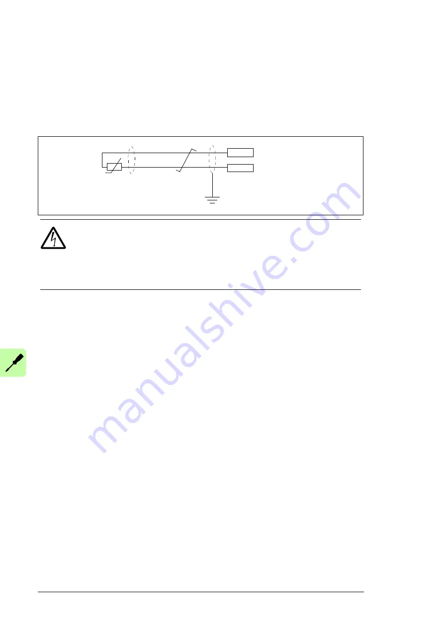
DI6 (XDI:6) as PTC sensor input
One PTC sensor can be connected to this input for motor temperature measurement as
follows. The sum of the sensor resistances must not exceed the threshold resistance of
the digital input at the motor normal operating temperature. Do not connect both ends of
the cable shield directly to ground. If a high-frequency capacitor of a few nanofarads (eg,
3.3 nF / 630 V) cannot be used at one end, leave that end of the shield unconnected. See
the firmware manual for the parameter settings.
DIIL input (XD24:1)
The DIIL input can used for the connection of safety circuits. By default, the input is
parametrized to stop the drive when the input signal is lost.
Drive-to-drive link (XD2D)
The drive-to-drive link is a daisy-chained RS-485 transmission line that allows basic
master/follower communication with one master drive and multiple followers.
Set termination activation jumper J3 next to this terminal block to the ON position on the
drives at the ends of the drive-to-drive link. On intermediate drives, set the jumper to the
OFF position.
Use shielded twisted-pair cable (~100 ohm, for example, PROFIBUS-compatible cable) for
the wiring. For best immunity, high quality cable is recommended. Keep the cable as short
as possible; the maximum length of the link is 100 meters (328 ft). Avoid unnecessary
loops and running the cable near power cables (such as motor cables).
WARNING!
As the inputs pictured above are not insulated according to
IEC 60664, the connection of the motor temperature sensor requires double or
reinforced insulation between motor live parts and the sensor. If the assembly
does not fulfill the requirement, the I/O board terminals must be protected against contact
and must not be connected to other equipment or the temperature sensor must be
isolated from the I/O terminals.
PTC
DI6
+24VD
T
“0” > 4 kohm
“1” < 1.5 kohm
I
max
= 5 mA
Summary of Contents for ACS880-04F
Page 1: ...ABB industrial drives Hardware manual ACS880 04F drive modules ...
Page 4: ......
Page 24: ...24 Introduction to the manual ...
Page 46: ...46 Guidelines for planning the mechanical installation ...
Page 102: ...102 Installation checklist ...
Page 106: ...106 Fault tracing ...
Page 135: ...Technical data 135 Declaration of Conformity ...
Page 136: ...136 Technical data ...
Page 140: ...140 Technical data ...
Page 142: ...142 Dimension drawings Standard configuration IP20 UL Open Type ...
Page 143: ...Dimension drawings 143 Drive module with options E208 and H370 IP20 UL Open Type ...
Page 144: ...144 Dimension drawings Drive module with options 0B051 E208 0H371 IP00 UL Open Type ...
Page 145: ...Dimension drawings 145 Drive module with options 0B051 E208 0H371 C217 IP00 UL Open Type ...
Page 146: ...146 Dimension drawings Drive module with options 0B051 0H371 IP00 UL Open Type ...
Page 147: ...Dimension drawings 147 Mounting plate 3AXD50000038119 ...
Page 148: ...148 Dimension drawings 3AXD50000038119 ...
Page 149: ...Dimension drawings 149 External control unit 3axd50000011687 ...
Page 150: ...150 Dimension drawings ...
Page 164: ...164 Safe torque off function ...