A&D Omniace III RA2300A Instruction Manual Download Page 179

20.    Specifications 

RA2300A Recorder (7001754-R01) 

20-11


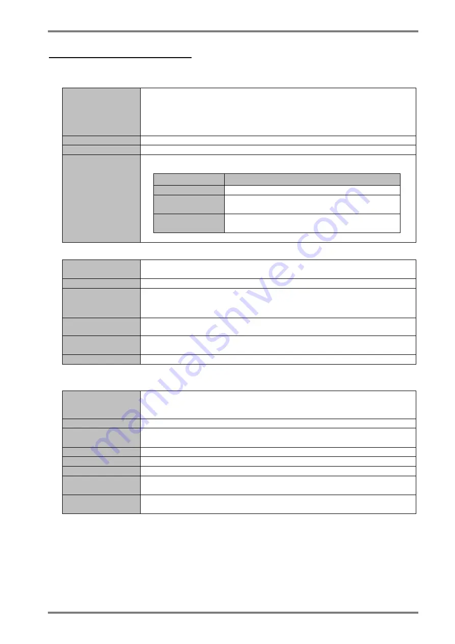
20.3.5.  Multi Recorder mode   


(1)  Memory Recording 

Recording speed 

The speed is set with sampling cycle. 

1 to 999 

s, 1 to 999 ms, and 1 to 100 s. 

1 to 999 

s, 1 to 999 ms, 1 to 100 s can be set for Users 1 and 2. 

*  Recording  started  by  external  clock  synchronization  (External  sampling 

input from remote unit) 

Memory size


2M data/CH


Block segmentation


1, 2, 4, 8, 16, 32, 64, and 128 segmentations


Recording 

operation


Starting with the Start button on the operation panel. Chose a mode from 

among Once, Repeat, and Endless. 

Recording mode


Recording operation


Once


Ends after recording once


Repeat


Ends  after  recording  the  number  of  times 

equivalent to the number of memory block


Endless


Continuously  records  until  the  operation  is 

stopped


* The Endless mode overwrites new data over old data. 

(2)  HD Recording 

Recording 

operation 

Recording  operation  starts  with  the  Start  button  on  the  operation  panel. 

Starting with a time trigger is also possible.


Recording drive


Internal HDD drive or external drive (USB supported)


Recording speed


1 to 999 

s, 1 to 999 ms, and 1 to 100 s

User1,User2.                           

* High-speed recording may not be available depending on the drive to be 

recorded and channels to be recorded. 

Recording method


Peaks  (Recording  max.  and  min.  values  among  sampled  values  by  1  μs  in 

HDD) 

Waveform  printing 

ON/OFF


Waveform  printing  on  chart  paper  with  recording  data  is  available.  The 

chart feed speed is the same as the speed of monitor printing. 

Data output format

  Only binary 

(3)  Pen Recording 

It is possible to print input signals directly on the chart paper. 

Paper 

Feeding 

Speed 

1 to 100mm/s, 1 to 100mm/min. 

Waveform printing synchronized with external clock, i.e. external sampling 

input in the remote unit, is possible. 

Time Axis 


Within ±0.01%(Error of time and printed grid, at ordinary temperatures)


Paper 

Feeding 

Accuracy


Within ±2%


Time Axis


10mm/div


Interpolation


Provided


Data recording


Peak detection with 1μs sampling


Time    Axis    dot 

pitch


10 dots/mm 

Amplitude    Axis 

dot pitch


8 dots/mm


Summary of Contents for Omniace III RA2300A

Page 1: ...RA2300A OmniaceⅢ INSTRUCTION MANUAL 1AV7001754 R01 ...

Page 2: ...OmniaceⅢ RA2300A Instruction Manual ...

Page 3: ...ening Package If opening the package in a warm room during the cold season open the package after it has reached room temperature to avoid any operational failure due to condensation on the surface of the product Examining Contents in Package This instrument is delivered after a thorough examination at the factory prior to shipment However please examine the product s condition and verify that no ...

Page 4: ...ven a fire Also in order to prevent electric shock and hazards such as a fire be sure to use only the AC power cable supplied with this recorder Protective Grounding Be sure to ground this recorder before supplying power Grounding is necessary to use this recorder safely as well as to protect the user and peripheral equipment from injury or damage Be sure to observe the following instructions 1 Th...

Page 5: ...ing of Back up Battery Cautions when Disposing This recorder includes a lithium secondary battery Lithium ion secondary battery When disposing this recorder remove the lithium secondary battery in advance Do not dispose of it in fire or disassemble The lithium secondary battery may explode when it is heated and organic electrolyte that may exude from it is harmful to human skin When disposing the ...

Page 6: ...ors 8 A hard disk drive HDD is installed in this product 1 Please don t power off during normal operation of HDD due to the risk of data destruction 2 Please have strong impact and shaking on this product due to the risk of HDD destruction 3 Please use it under 5 to 40 conditions according to the danger of HDD destruction 9 This recorder uses a touch panel When touching the panel do not use a shar...

Page 7: ...nty Limited Warranty 1 Warranty period One year from our shipment 2 Warranty period We will repair the defects of our product free of charge within the warranty period however this warranty does not apply in the following cases 1 Damage or faults caused by incorrect use 2 Damage or faults caused by fire earthquake traffic accident or other natural disasters 3 Damage or faults caused by a repair or...

Page 8: ... measuring with memory recorder or transient recorder measured data is recorded in this memory k lower case K upper case A unit of numerical value k is used to represent 1000 such as 10 kg K is used to represent 1024 such as 4 K data Liquid Crystal Display This recorder has a TFT color LCD for display There may be cases where the light of pixels does not come on or off in the LCD In addition the L...

Page 9: ...saved in HDD will be infected by viruses In case there are possibilities that virus infected files are saved in HDD please eliminate the virus by going through the following procedures If other PCs connected to the same network access the subject file the PC could become the source of infection Please set up one to one network environment and run anti virus software from a PC targeting the HDD of ...

Page 10: ... 2 5 Other Optional Equipment 1 4 2 Name and Function of Each Block 2 1 2 1 Overview of Blocks 2 2 2 2 Display Block 2 3 2 3 Operation Panel 2 4 2 4 Right side Block 2 6 2 5 Upper Surface Block 2 7 3 Pre measurement Procedures 3 1 3 1 Before Switching on the Power 3 2 3 1 1 Usage Environment 3 2 3 1 2 Before Connecting AC Power Cable 3 2 3 1 3 AC Power Cable 3 3 3 2 Paper Loading 3 4 3 2 1 Paper R...

Page 11: ...scription of Icons 9 3 9 2 2 Memory Recording Condition Setup Block 9 4 9 3 Recording Operation 9 7 10 HD Recorder 10 1 10 1 Overview of HD Recorder Mode 10 2 10 2 Recording Condition Setup 10 3 10 2 1 REC Icon 10 3 10 2 2 HD Recording Setup Block 10 4 10 3 Recording Operation 10 7 10 3 1 Start of Measurement 10 7 10 3 2 To Finish Measurement Forced Termination 10 7 10 3 3 Waveform Chart Printing ...

Page 12: ...gger Mode 13 7 13 4 1 Trigger Mode OR 13 7 13 4 2 Trigger Mode AND 13 7 13 4 3 Trigger Mode WINDOW 13 8 13 4 4 Trigger Mode OFF 13 9 13 5 Trigger Filter 13 9 13 5 1 Trigger Filter 13 9 13 6 Trigger Settings for Event Amp 13 10 13 7 Trigger Settings for Event unit 13 11 14 Replay Display 14 1 14 1 Overview of Replay Monitor 14 2 14 2 Replay Data Selection 14 3 14 3 Waveform Display Region 14 4 14 3...

Page 13: ...t Mode 16 4 16 3 3 Setup Value Save 16 5 16 3 4 Initialize 16 5 16 4 File Operations 16 6 16 4 1 Create Folder 16 7 16 4 2 Copy 16 7 16 4 3 Delete 16 7 16 4 4 Read 16 7 16 4 5 Save Text 16 8 16 4 6 Save Env 16 8 16 4 7 CSV save 16 8 16 4 8 Save Memory 16 9 16 5 Recording Settings 16 10 16 5 1 Recording Channels 16 10 16 5 2 Data No Setting 16 11 16 5 3 Print Settings 16 11 16 5 4 Recording Speed T...

Page 14: ...tor Pin Location 17 9 17 5 RS 232C Unit RA23 142 17 10 17 5 1 Names of each parts and their functions 17 10 17 6 AC Bridge Excitation unit RA23 143 17 11 17 6 1 Names of each parts and their functions 17 11 17 6 2 Set up for Synchronization 17 11 18 Maintenance and Cleaning 18 1 18 1 Handling and Storing Recording Paper and Data 18 2 18 1 1 Storing the Recording Paper 18 2 18 1 2 Caution for Handl...

Page 15: ...t 20 12 20 5 Standard Function 20 12 20 6 Interface 20 12 20 6 1 LAN Standard 20 12 20 6 2 USB Standard 20 12 20 6 3 TRIG IN TRIG OUT Standard 20 12 20 7 Remote Unit RA23 144 Optional 20 13 20 8 Event Unit RA23 145 Optional 20 14 20 9 Event Box RA23 146 Optional extras 20 15 20 10 RS 232C Unit RA23 142 Optional 20 16 20 11 AC Bridge Power Supply Unit RA23 143 Optional 20 16 20 12 English Operation...

Page 16: ......

Page 17: ...1 RA2300A Overview ...

Page 18: ...modes are provided such as Pen Recorder enabling a pen recorder like operation HD Recorder enabling long time recording and X Y Recorder displaying input signals with 1ch in the X axis direction and 3ch in the Y axis direction This allows you to choose an appropriate function according to your purpose Standard LAN and UEB interface LAN 100BASE T for data communication and USB for storage devices U...

Page 19: ...t AP11 103 HSDC 2CH AC Strain Amp Unit AP11 104 104A ACST Event Amp Unit AP11 105 EV 2CH TC DC Amp Unit AP11 106 106A TCDC TC DC Amp Unit AP11 107 TDC F V Converter Unit AP11 108 FV 2CH Vibration RMS Amp Unit AP11 109 RMS 2CH DC Strain Amp Unit AP11 110 DCST 2CH Zero Suppression AP11 111 HRZS 1 2 3 Standard Accessories Display in Japanese and 100VAC Name Type No Rating Quantity AC power supply 031...

Page 20: ... Consumables Name Type No Rating Recording chart paper YPS106 Roll chart paper 219 5 mm x30 m 5 volumes per box Recording chart paper YPS108 Roll chart paper 219 5 mm x30 m 5 volumes per box With 300 mm pitch perforated line Remaining length indication print pitch 300mm 99 to 01 Recording chart paper YPS112 Z fold paper 219 5 mm x 200 m fold width 300 mm Remaining length indication print pitch pag...

Page 21: ...2 Name and Function of Each Block ...

Page 22: ...w of Blocks The RA2300A consists of the following blocks Front view Upper Surface For details 2 4 page For details 2 3 page For details Operation panel Display block Left side Right side For details Printer block Amp block Grip Interface block Optional 2 6 page 2 7 page ...

Page 23: ...rs The contents for amplifiers differ depending on the amplifiers that are installed Input Monitor screen The buttons on the operation panel switches the screen display the touch panel buttons on a displayed panel makes settings for input units recording conditions acquisition and triggers The conditions of the signals that are input can be observed on the display There may be few dots that always...

Page 24: ...nt speed of cursor and scroll This button is used to change the scrolling speed for cursor or waveform This change is made by changing values on the screen 4 Jog dial Continuous value changes cursor movement on the monitor and waveform scrolling Value can be continuously changed by rotating the jog dial On the replay monitor smooth cursor movement and waveform scrolling can be made Waveform select...

Page 25: ...splay format can be set 12 System Displaying system screen The following settings are available Measurement mode that decides measurement method Maintenance that sets date RS 232C LAN and Communication that sets remote Buttons related to recording and printing 13 Chart Feed Feeding chart recording paper While this button is pressed chart recording paper is fed 14 Screen Copy Hard copy for screen P...

Page 26: ...dditionally signal from this terminal is used to monitor the status of the trigger 6 LAN This is a connector for LAN connection This connector is useful when a communication between personal computers is made 7 USB This is a USB connector Memory devices such as USB memory or external drives can be connected 8 AC bridge power switch INT EXT OSC terminal This is INT EXT switch for AC bridge power un...

Page 27: ...RA23 142 optional is inserted in this portion Connection to external machines such as the host computer is made 4 EVENT Event unit RA23 145 optional is inserted in this portion Sixteen event signals can be input 5 REMOTE Remote unit RA23 144 optional can be inserted in this portion Stat or stop for recording printing feed marking or synchronous operation can be made 2 3 4 5 1 ...

Page 28: ......

Page 29: ...3 Pre measurement Procedures ...

Page 30: ...essive humidity due to exposure to direct sunlight or proximity to heating fixtures 2 Damp or wet place 3 Places with salty oily or gaseous atmosphere 4 Humid or dusty place 5 Places subject to strong vibration or shock 6 Places subject to voltage surges due to an electromagnetic field 7 To protect from an excessive internal temperature this recorder is provided with ventilation holes These holes ...

Page 31: ...at of the user and peripheral equipment If AC power cable that comes with this recorder is connected to a 3 pin power outlet equipped with a protective conductor pin the recorder is automatically grounded 3 1 3 AC Power Cable The AC power cable that is included in this recorder 0311 5044 100 VAC system 2 5 m is a 3 pin type which has the round pin at the center for protective grounding CAUTION ...

Page 32: ...ed the recording quality cannot be guaranteed and the normal operation of the paper feed may be affected Do not use the portion of the new roll that is covered with tape as colors may not be printed normally on this area 2 Open the cover of the recording paper section by raising the lock 3 Load the paper in the compartment slots following the recorder guide Press the paper holders into the slots u...

Page 33: ... 3 2 2 Loading z fold paper To use z fold paper YPS112 a z fold paper case RA12 103 sold separately is required Z fold paper YPS112 Length 200 m Folded width 30 cm To indicate how much paper is remaining a page number 669 to 000 is printed on each page Use only the z fold paper prepared exclusively for this recorder by our company If other types are used the recording quality cannot be guaranteed ...

Page 34: ... case open the plastic bag and take out the piece of cardboard covering the paper Use the top cover of the case as a receptacle for the recorded paper 2 Place the paper in the stock box with the thermally sensitive side the side with blue numbers printed on the edges facing up 3 Position the stock box so the paper flap edge non folded edge is facing toward you and insert the box into the case open...

Page 35: ... 10 Insert the paper adapter in the slots of the cover Press the paper adapter with the paper wound on it into the slots until a click is heard Insert the paper wound on the adapter in the opening under the platen roller black roller of the recording section and pull it out about 10 cm Pull the paper wound on the paper adaptor out the cover as shown route Insert the paper adaptor with the paper wo...

Page 36: ...ing the paper in front of the recording section cover to use as a paper receptacle To ensure smooth paper output fold one or two sheets into the receptacle before use Note that although z fold paper usually folds automatically as it is output some environmental conditions such as a humid atmosphere or the setting location may cause the paper not to fold normally Pull the paper wound on the paper a...

Page 37: ...n off the power 2 Remove the power cable 3 Remove input cables connected each amp unit 4 Check if the power switch is off Tighten each amp fixed screw on the upper and the lower using a screwdriver to fix the unit Screwdriver edge width 0 65 mm or less Loose the screws until removing the connection of this recorder Take care over loosing of the screw not to remove the unit 5 Pull out the amp unit ...

Page 38: ...After confirming that these points above are all yes turn on the recorder following to the steps below 1 Connect the inlet side of the AC power cable to the AC socket of this recorder Connect the inlet side of the accessory AC power cable to the AC socket on the power supply panel of this recorder 2 Connect the plug of the AC power cable to the power outlet 3 Turn on the recorder power Turn on the...

Page 39: ... is properly displayed on the screen The Input Monitor screen will be displayed immediately after power application 2 Confirm that the paper is fed correctly This can be confirmed by pressing the Feed key on the operation panel If no paper is fed check whether the cover is closed properly or not 3 The pre measurement procedures are completed Press Feed ...

Page 40: ......

Page 41: ...4 Operation Flow Flow of Measurement Basic Settings and Operations ...

Page 42: ... data to be recorded Refer to Chapter 7 for details Trigger settings Set the trigger for activating to be recorded Refer to Chapter 13 for details Measurement mode settings Select the mode appropriate for the kind of object desired from the 5 available measurement modes To print the recording chart paper Pen recorder mode Refer to Chapter 8 for details To store high speed events in memory Memory r...

Page 43: ...ing items and icons on the screen As the display is of a touch panel settings can be made by directly touching the keys on the display screen 4 2 1 Explanation of Basic Screen Settings The setting screen is broadly divided into the control waveform monitoring and setting blocks Display Operation panel 3 Waveform monitoring block 2 Setting block 1 Control block ...

Page 44: ...form monitor block Because the input waveform monitor is always displayed on the normal setting screen settings can be made while observing the input signals 4 2 2 Explanation of setting keys Each setting item displays a different image depending on the input method to be used The various input methods are explained below Jog key When the jog dial image is displayed in the setting block the jog di...

Page 45: ...e prohibited Rotary knob Rotary knob is a knob type key used for the range setting for input amplifiers Value changes by rotating the jog dial after the color of the key changes by touching the key entry state of the jog dial The highlighted value is the current value to be set Adjustment knob This knob is used to change the base line position for an input amplifier Value changes by rotating the j...

Page 46: ...meral input window Use this window to enter numerical values Character input window Use this window to input character strings 1 Window title This displays contents of the setting item 2 Input display section This section displays input character strings and cursor position To register the setting press the EXEC key The window then closes Numeric input key Allowable setting range Current setting C...

Page 47: ...cter strings to convert into kanji can be input by pressing the IME key When the key is pressed kana input mode using Roman character is changed after the key is highlighted To convert kana into kanji press the Blank Conversion key To select among kanji list press the Arrow key or Blank Conversion key To select among kanji list on the panel touch the panel directly To confirm the selection press t...

Page 48: ......

Page 49: ...5 Input Signal Monitor Observing Input Signals ...

Page 50: ...input use the Input Signal screen This screen displays the signals that are input in real time The waveforms can be frozen as necessary The signals can be seen in Amp Recording Condition and Trigger screens too When the measurement mode is Pen Recorder or X Y Recorder howerver special screen appears TIPS Amp setup screen Pen recorder screen ...

Page 51: ...ition 3 Position marker This is zero position for all analog amps 4 Amplitude scale This is amplitude scale for analog amps This scale can be hidden depending on the setup Chapter 15 Display and Printing 5 Signal name Indication of signal name that are entered by user can be made The signal name can be hi dden depending on the setup Chapter 15 Display and Printing Chapter 16 System Setup 6 Value i...

Page 52: ...nput Monitor Fixed speed for input monitor Enabled Enabled Enabled Chart Feed Speed Monitor displaying same speed as the chart feed speed Disabled Enabled Enabled Memory Sampling Speed Monitor displaying same speed as the memory sampling speed Enabled Disabled Enabled HD Recording Speed Monitor display same speed as the HD recording speed Disabled Enabled Enabled Monitor speed setting becomes disa...

Page 53: ...etween No and Digital Value 14 Timer indication f the timer printing is set the recording time for the next session If it is not set nothing is indicated 16 System Settings 15 Time This portion indicates the current time 16 Key lock By setting this function key entries on the operation panel are blocked Pressing this button switches key lock on and off 16 System Settings Key lock OFF Key lock ON ...

Page 54: ......

Page 55: ...6 Auto Setup Automatically Setting Recording Conditions ...

Page 56: ...automatically sets the range of analog amps The auto range function is available in the following amps Unit Name Model Abbreviation 2CH High Resolution DC Amp Unit AP11 101 HRDC 2CH FFT Amp Unit AP11 102 HSDC 2CH High Speed DC Amp Unit AP11 103 FFT 2CH AC Strain Amp Unit AP11 104 104A ACST 2CH TC DC Amp Unit AP11 106 106A TCDC TC DC Amp Unit AP11 107 TDC F V Converter Unit AP11 108 FV 2CH Vibratio...

Page 57: ...vailable Memory sampling rate Available Available File recording rate Available X Y sampling rate Available Adjusted Not adjusted In the X Y Recorder mode the auto sampling does not function For X Y data sampling rate make adjustment with seeing the monitor 6 3 2 Adjustment Range Chart feed speed Memory sampling speed File recording speed 100 mm s 1 ms 1 μs 10 μs 50 mm s 2 ms 2 μs 100 μs 20 mm s 5...

Page 58: ......

Page 59: ...7 Amp Units ...

Page 60: ...nel To change the channel use the Scroll button 1 Channel Channel number amp type and waveform color are indicated on this button Pressing this button displays the Amp Details screen making more detailed setup 2 Amp setup block This block is used to set basic settings for amp As contents differ depending on the amp type refer to the descriptions of each amp 3 Information display Setup information ...

Page 61: ...ame type of amp can be made Pressing the button highlights this button indicating the batch setup is effective In addition the Channel buttons of target channels of batch setup highlight too If specific channels should setup through batch setup cancel the highlight of the channels by pressing the Channel button that will not be set To set through the batch setup highlight the target channels again...

Page 62: ......

Page 63: ...8 Pen Recorder Recording Low speed Signal for Long Time ...

Page 64: ... tab in the System screen Measurement mode setting is made on the Startup screen that is displayed upon the startup Depending on the startup screen the Startup screen may not be displayed As the Pen Recorder mode only performs waveform printing on a chart recording paper Even the Input Signal Amp Recording Condition and Trigger buttons are pressed the screen display does not change NOTE System scr...

Page 65: ...his block is the same as the chart feed speed For more details see Chapter 5 Observing Input Signal 2 Amp setup block This block is used to set amp unit For more details see Chapter 7 Amp Units 3 Chart feed speed These buttons are used to set chart recording paper feed speed Value is set by pressing a button Through User 1 and User 2 buttons user can set arbitrary feed speeds For more details Chap...

Page 66: ... 4 9 01 H1 HRDC ON A 100mV 0s 5s Chart speed 10ms 1s div CH1 mV 50 000 40 000 30 000 20 000 10 000 0 0000 10 000 20 000 30 000 40 000 150 000 2 System annotation below 7 Measurement information 5 Scale 1 Waveform printing 2 System annotation above 3 Mark printing 9 Channel annotation 8 Page annotation 6 Time axis 4 Signal name AAAA BBBB CCCC AAAA BBBB CCCC AAAA BBBB CCCC AAAA BBBB CCCC AAAA BBBB C...

Page 67: ...System Setup 7 Measurement information Character strings specified by user are printed before waveforms are printed To set printing ON OFF or character strings see Chapter 16 System Setup 8 Page annotation Following system annotation character strings defined by user are printed over waveform printing To set printing ON OFF or character strings see Chapter 16 System Setup 9 Channel annotation Reco...

Page 68: ......

Page 69: ...9 Memory Recorder Recording High speed Signals ...

Page 70: ...py or file saving Backup Filing is also available In addition replay of waveforms on the monitor is possible To set the RA2300A to the Memory Recorder mode use the Measurement Mode tab on the System screen Mode setting is can also be made on the Startup screen that is displayed upon the startup Depending on the startup screen the Startup screen may not be displayed Operation panel Measurement mode...

Page 71: ... stops its operation Setup can be made during recording 9 2 1 Description of Icons The icons signify recording settings and status 1 Memory Recording 2 Auto Copy 3 Backup Filing 4 Others Stop OFF White As waveform chart printing HD recording does not operate no indication is made Stop ON Green Trigger wait Yellow None None Measuring Amber Error Red 1 Memory recording status indication 2 Setting fo...

Page 72: ... rate Block count The block count is calculated based on the block size Memory block size can be expanded to more than 4 MW by limiting the number of channel for recording To limit the number of channel for recording see 16 System Setup 3 Memory block and status indication Block number to be recorded and data existence is indicated Block number can be changed using the jog dial NOTE 5 Pre trigger ...

Page 73: ...ngth after the trigger is 30 ms resulting in shorter data length than pre set length 6 Memory recording operation These buttons are used to specify the memory recording operation Recording operation Description Once Operation closes after recording of one block is finished Repeated Recording operation repeats for the number of blocks It finishes when all blocks are recorded Endless Recording opera...

Page 74: ...ck box is ticked a folder can be made by user The data save destination will be under the folder c ON OFF for creating folder everyday When the check box is ticked starting time is referenced and folder is created everyday The data save destination will be under the folder d Arbitrary file name Limited to the top four letters Top four letters for the save file is designated The file name will have...

Page 75: ...n settings see 13 Trigger Setup If the Stop button is pressed and forcible termination is made before the trigger detection data recording is made up to the size set by the pre trigger Example Under pre trigger of 20 ms if the recording is forcibly terminated before the trigger detection the recording length is up to 20 ms 2 Data recording after trigger The amount of data specified by the pre trig...

Page 76: ......

Page 77: ...10 HD Recorder Recording Data in Internal HDD ...

Page 78: ...et the recorder in the HD Recorder mode use the Measurement Mode tab in the System screen Settings of measurement mode can be made on the Startup screen displayed upon the startup The startup screen does not appear depending on the setup The drive for data recording is fixed to the internal HDD only For details on data output to the USB storage see Replay Screen Data Output or System File Operatio...

Page 79: ...ation Setup can be made during recording 10 2 1 REC Icon The icons signify recording settings and status 1 Chart Printing 2 HD Recording 3 Others Recorder stop OFF White As memory recording does not operate indication is invalid Recorder stop ON Green Trigger wait Yellow None Operating Amber Error Red Remark Pressing waveform chart printing ON OFF is switched Setup while the recorder is recording ...

Page 80: ...inary has fsd as its extension d File name Arbitrary file name Limited to the top four letters Top four letters for the save file is specified The file name will include designated top four letters and four digit serial number The extension has fsd for the binary save and csv for the CSV save 2 Recording rate Recording rate can be set Recording time changes if the recording speed is changed Check ...

Page 81: ...h of time will result 5 Recording operation HD recording operation can be made with trigger detection Setup item Contents Recording start with start button When the Start button is pressed recording begins Start trigger After the Start button is pressed recording starts upon trigger activation Marking upon trigger detection Up to newest 128 trigger points can be memorized The marking points can be...

Page 82: ... Waveform chart printing Settings related to waveform chart printing are made a Waveform ON OFF ON OFF for waveform chart printing is made Changes during operation can be made b Same printing speed as recording speed When the check box is ticked the waveform chart printing speed is automatically set to the speed the same as current recording speed To separate the recording speed from the chart fee...

Page 83: ...eration finishes with an error For HD recording see 10 4 HD Recording Specifications 10 3 2 To Finish Measurement Forced Termination Pressing the Stop button on the Operation Panel executes forced termination If recording length is specified operation completes when specified number is recorded 10 3 3 Waveform Chart Printing During HD recording waveform chart printing is started and stopped as nec...

Page 84: ...mple Recording length 100 000 Data format peak Number of recording channel 16 Size 8 192 100 000 x 4 x 16 6 408 192 bytes 10 4 2 Recording Speed Execution Restriction The following restriction may be subjected in settable range in HD recording rate depending on the data format and the number of recording channels For mat Recording rate Number of recording channel 1 2 3 4 5 6 7 8 9 10 11 12 13 14 1...

Page 85: ...11 Multi Recorder Separately Executing Waveform Printing Memory Recording and HD Recording ...

Page 86: ...h the event jump function of replay monitor switching between HD recording data and memory recording data can be switched to confirm the data being recorded For the event jump function see 14 Replay Display In order to set the recorder to the Multi Recorder mode use the Measurement Mode tab in the System screen Besides setting of measurement mode can be made in the Startup screen displayed upon th...

Page 87: ...an be made during recording 11 2 1 REC Icon The icons signify recording settings and status Chart Printing Memory Recording Backup Filing HD Recording Others Stop OFF White NA Auto copy does not operate Icons are invalid Stop ON Green Measuring Amber Error Red Pressing chart recording button can switch ON OFF for chart printing Waveform chart printing and status indication Memory recording status ...

Page 88: ...de difference Data output related settings Setting procedure in the screen above is the same as that in 10 HD Recorder However the following settings are not available due to the recorder mode difference Start trigger Once and Repeat Recording format Waveform chart recording related settings File output path Waveform recording Memory recording setup block The setup steps are the same as in 9 Memor...

Page 89: ...ary file name Top four letters An individual file name can be set in memory recording and file recording The file name consists of eight letters specified four letters for the first half and automatically assigned four letters for the latter half fsd binary save is appended as an extension Memory recoding setup block Settings for memory recording can be made HD recording setup block Settings for H...

Page 90: ...ti recording begins when the Start button on the Operation Panel is pressed Recording set through waveform printing Memory Recording or HD Recording can be made simultaneously For memory recording see 9 Memory Recorder For HD recording see 10 HD Recorder 11 3 1 Error Generation Error that may occur during multi recording and operations are described as follows Error Operation File error HD recordi...

Page 91: ...12 X Y Recorder ...

Page 92: ...addition the measurement mode settings can be made on the Startup screen that is displayed when the recorder is started up The Startup screen may not be displayed depending on the settings Since the X Y Recorder is a mode that is specialized to the X Y printing the same screen is displayed even screen buttons of Input Signal Amp Recording Condition and Trigger Press OK Measurement mode selection P...

Page 93: ...fter called pen mark 2 X axis scale Measurement scale specified to the X axis is displayed 3 Y axis scale Only one measurement scale specified to the Y axis is displayed The scale to be displayed can be changed using Y scale button 4 Amp setup The setup for the channel specified to X and Y axes can be made For how to use amp units see 7 Amp Unit 5 Print Icon 7 X Y Recorder control block 8 X Y axis...

Page 94: ...Y recording is a folder in the internal HDD The file name is created based on the time that starts recording Example D RA2300XY XY041201 fsd 7 X Y Recorder Control Block a Sampling rate This button is used to set data sampling rate for X Y recording b Grid This button is used to set grid to ON or OFF in the X Y monitoring and X Y printing For grid pattern for the X Y printing see 16 System Setup c...

Page 95: ...play ON or OFF can be set for three Y axis channels Pen down draws waveforms Pen up does not draw waveforms Pen mark always appears regardless of the up down setting However the pen mark appears on the X Y monitor only and does not appear on the X Y printing b Pen up and down Y axis 1 a Channel settings Y axis 3 b Pen up and down Y axis 2 b Pen up and down Y axis 3 a Channel setting X axis a Chann...

Page 96: ...trictions in X Y printing Setup changes cannot be made X Y monitor clear and stop cannot be made Screen movement cannot be made Press the STOP button and finish the X Y printing to execute the operations above 12 3 2 Exception Error An error may be generated during X Y printing due to the following reasons Paper out This error is generated when the chart paper is run out Fill in a chart recording ...

Page 97: ...13 Trigger Settings Capturing Target Data to be Recorded ...

Page 98: ...either of two channels that are set for trigger source satisfies the trigger condition The OR setting for all channels are also available Example Both of slopes for CH1 and CH3 are set to rising edge 13 1 2 Trigger Mode Operation at AND Trigger is generated all channels that are set for trigger source satisfied the trigger condition The AND setting for all channels are also available Example Both ...

Page 99: ... can be made for all analog channels A trigger is generated upon satisfying of either of the trigger settings Example When CH8 is set to OUT 13 1 4 Trigger Mode Operation at OFF Trigger caused by a signal input into amp is not made Only the manual and external triggers are effective When printing is made only the trigger made after the startup is effective If the trigger condition is satisfied bef...

Page 100: ...he operation panel generates a trigger irrespective of other trigger settings 13 2 2 External Trigger TRIG IN Trigger is generated by the falling edge of a 0 to 5 V signal To use enter a signal into TRIG IN in the recorder 13 2 3 External Trigger Output TRIG OUT When a trigger is generated the L level of the signal which has TTL level and 10 ms pulse width is output from the TRIG OUT terminal TRIG...

Page 101: ...al Trigger Input Output Circuit External trigger input circuit Input signal 0 to 5 V voltage signal falling edge External trigger output circuit Output signal TTL level active LOW Pulse width Approx 10 ms TRIGGER IN 100Ω 10kΩ 3 3V 3 3V トレラント 5V 機能付 ロジック 低電圧 5V TRIGGER OUT 330Ω 3 3V トレラント 5V 機能付 ロジック 低電圧 ...

Page 102: ... Pressing the Trigger button on the Operation Panel opens the Trigger Settings screen Trigger setting Operation panel Target channel The color of this portion changes its color by touching Then signal level can be set by dialing the jog dial Pressing this portion switches the slope Trigger detection at rising edge of a signal Trigger detection at falling edge of a signal OFF Trigger settings scree...

Page 103: ...ND Trigger is generated upon the satisfaction of the trigger condition for all channels that are set as the trigger source Trigger setting Trigger setting Setting the trigger generation level Selection of the trigger source channels to be set and settings of rising or falling edge for the signal is made Selection of the trigger source channels to be set and settings of rising or falling edge for t...

Page 104: ...n be made for all analog channels A trigger is generated upon satisfying of either of the trigger settings Touching this portion makes jump to the first channel Touching this portion makes channel increment one by one Setting the upper level Touch the screen and turn the jog dial to set the signal level Setting the lower level Pressing this portion switches the slope Trigger detection at rising ed...

Page 105: ...gger condition is satisfied before the start of recording the status enters into the wait for next trigger condition 13 5 Trigger Filter 13 5 1 Trigger Filter After the trigger condition that is set is satisfied the trigger is activated after this satisfied condition continues for a specified period of time This function is effective to eliminate noises whose pulse length is relatively short In th...

Page 106: ...er conditions In the event amp a trigger is activated when first trigger condition is satisfied If the trigger condition has been satisfied a trigger will be not be activated Especially for example one channel has already been satisfying the trigger condition in the OR mode the trigger will be activated even when other channel s trigger condition is satisfied Trigger conditions for channels 1 to 8...

Page 107: ...satisfied when the input voltage reaches 2 5V or higher L The L condition is satisfied when the input voltage becomes 0 5 V or lower NO Exempting from trigger conditions Trigger conditions for channels 1 to 8 are set H L NO can be set If NO is set the check box is not displayed Trigger settings are made when the check box is ticked AND When all trigger conditions that have been set are satisfied a...

Page 108: ......

Page 109: ...14 Replay Display Displaying Recording Data ...

Page 110: ...me axis jump 14 6 Jump 7 Time Axis Scaling Enlarges or compresses time axis 14 7 Time Axis Magnification 8 X Y Display Switches X Y waveform display 14 9 X Y Waveform Display 9 Y T Display Switches Y T waveform display 10 Position Indicates zero position for each signal 11 Scale Displays scale for amplitude axis 15 Display and Print 12 Signal Name Signal name indication 15 Display and Print 13 Dig...

Page 111: ...de through direct touching 3 Data selection This changes selected data file 4 Recording information This portion lists the information of recorded data that is selected in the data list This information may be used as a reference for data selection The following steps can change the reference data in the common folder 1 Press the left portion of the Data Selection button to activate jog dial The f...

Page 112: ...y region can be shifted The auto scroll buttons at both sides allows one direction scrolling Shift through operation panel Press the Scroll button on the operation panel to make scrolling effective When scrolling becomes usable the LED of the Scroll button comes on Turning the job dial shifts the display region Shift through jump faction Jump to the trigger detection point or making point is avail...

Page 113: ...ing data is the peak format one data consists of two values maximum and minimum value To specify the digital value in either of maximum and minimum values open the Display Printing screen For more details 15 Display and Printing 14 4 2 Cursor Display Information This portion indicates the position information of cursors X1 and X2 and the time difference between cursors T Time axis display format c...

Page 114: ... Screen appears The contents differ depending on the amp type Operations of Signal Setup screen is the same as those of the Amp screen For more details see 7 Amp Units TIPS Analog amp setup screen Waveform ON OFF setting Zero position setting Physical unit conversion setting Other recording condition display Event amp setup screen Waveform ON OFF setting ON OFF setting by signal Event waveform adj...

Page 115: ...e to the start point Cursor X1 X2 Jump to current cursor position 14 6 2 Time Jump Jump is made after the waveform display position is specified Specify the time using the Time tab on the Jump screen Pressing the Apply and OK buttons execute a jump When the Apply button is pressed the jump screen does not close the Jump screen even after the jump execution To execute jump continuously this button ...

Page 116: ...he result Operation steps for the maximum and minimum values search are as follows 1 Use the Max and Min tab on the jump screen 2 Specify the search range Choose All or Between Cursors Press a button begins searching and after the search a list appears 3 Select a channel Select a target channel Selection can be made through a direct touch of listed portion 4 Jump to maximum value or minimum value ...

Page 117: ...e mark is not found jump to the start end point is made 3 Jump to link data is made When this button is pressed after the making jump is made while the data file extension of IDX recorded in the Multi Recorder mode is displayed a jump to the link data memory recording data is made 14 7 Time Axis Magnification To enlarge or compress the time axis press Time Axis button The following screen appears ...

Page 118: ...rigger point is selected specify percentage To output all select Specifying in percentage in reference to the trigger point and choose 100 for percentage 14 8 2 Specifying File Save Format Use the 2 button to specify the format at file save Select binary or CSV If CSV is selected the number of skip and delimiter can be specified The file extension will be DRT that is output in the binary format Th...

Page 119: ...xtension will be fixed Binary save DRT CSV save CSV 14 8 6 Execution of Data Output Output to chart paper is made with the 6 button File save is made with the 7 button Output can be stopped with the Stop button on the Operation Panel If the file save operation is terminated the file being saved will be discarded During the data output the other operations do not start Do not disconnect the connect...

Page 120: ... for Y T waveform display For more details see 14 2Replay Data Selection The X Y display is available only in the Sample format data Choose the Sample format data accordingly 2 X Y Waveform Printout The X Y waveform being displayed will be output to the chart printing paper Operations during outputting are disabled but forcible stop can be made with the Stop button on the Operation Panel 3 Signal ...

Page 121: ...15 Display and Printing Settings for Monitor Display and Printing ...

Page 122: ...rm recording frame only the first channel s scale will be indicated To display the next channel turn off the channel display for the first channel 15 1 2 Grid Display Pressing the button 3 on the Display and Printing screen turns on or off the grid indication 15 1 3 Digital Value Display To indicate digital values of each channel tick the check box for 4 on the Display and Print screen Also when P...

Page 123: ...lect the frame made by waveform segmentation The upper side of the frame is the first frame c Frame size Size for amplitude direction for a frame can be specified d Display channel Selection of channel to be indicated in the frame is available The frame size is limited to the effective printing range 216 mm including the entire frame size and margins 15 1 7 Thumbnail Channel selection of the thumb...

Page 124: ......

Page 125: ...16 System Setup Other Functions ...

Page 126: ...6 4 6 Environment Save 16 9 16 4 7 Readout 16 9 16 5 Recording Settings 16 10 16 5 1 Recording Channels 16 10 16 5 2 Data No Setting 16 11 16 5 3 Print Settings 16 11 16 5 4 Recording Speed Table 16 12 16 5 5 Time axis Representation 16 12 16 5 6 Timer Recording Settings 16 12 16 5 7 External Sync Rate Setting 16 13 16 6 Communication Settings 16 14 16 7 Auxiliary Settings 16 16 16 7 1 Buzzer Clic...

Page 127: ...that is stored in a memory is saved The data that is saved resumes at the next startup of the recorder 16 2 2 USB Drive Disconnection This button is used to disconnect the USB storage devices that are connected to this recorder After this button is pressed message of You can disconnect USB devices appears Then disconnect the USB device USB storage device disconnection should be made while recordin...

Page 128: ...lay upon Startup This screen can be opened upon startup when the check box is ticked If this recorder is used under the condition whose measurement mode is fixed recording can be made immediately after the recorder is turned on when this check box is not ticked 16 3 2 Measurement Mode Measurement mode can be changed Pressing the measurement mode button displays the Window for confirmation To execu...

Page 129: ...f this recorder can be resumed to the factory default Also the item to be initialized can be set 1 Recorder setup data The setup status can be resumed to the factory default 2 Setup data related to communication Communication setup can be initialized to the factory default 3 Annotation Deletion of user page annotation measurement information and signal name are made 4 Internal memory data Data in ...

Page 130: ...ected item is highlighted Change can be made through direct touching 3 Batch selection Select two or more files in a folder Copy or Delete is available for batch selection file In case of Bulk Delete data is very important for Recorder So system shows on the screen Delete or keep for comfermation individually 4 Other file processing Several file processing is made for the file in the target refere...

Page 131: ...ion is made in the File Operation screen 2 CSV save The source file for copy as a data file with the FSD FPP IDX or DRT extension can be saved as the CSV format Time axis range thinning out and delimiter code can be specified in Output Settings in the Replay screen For more details see Chapter 14 Replay Display 16 4 3 Deletion Selected files or folders are deleted The following screen appears by p...

Page 132: ...on Recording information for the data selected is displayed Data selection can be made based on this recording information 4 Block data selection Selection position for listed data is changed 5 CSV save Memory block data can be saved as the CSV format data To save data as CSV file add a check mark to save data as a binary format do not add a check mark Time axis range thinning out and delimiter co...

Page 133: ...he extension of file to be saved is ENV for environment information and TXT for text information The file made by character strings only has an extension of txt A text editor can read this file accordingly Conversely a text file edited by a personal computer can also be read by the RA2300A If an environment file is read by another RA2300A the setup in which hardware configuration is different is d...

Page 134: ... Rate Setting 16 5 1 Recording Channels By restricting the number of recording channel block size per channel for memory recording can be increased In the System screen use the Recording Settings Pressing Recording Channel displays the following table Channels excluded from the recording target are neglected Even a unit is installed nothing is displayed If recording channel settings are changed th...

Page 135: ...acter string entry 1 Printing Item ON OFF Whether to print or not print can be determined using tick box for channel mark system annotation channel annotation time axis scale measurement information signal name and user annotation 2 Annotation character string entry Character strings for measurement information signal name and user annotation can be made A text file that is edited by a personal co...

Page 136: ...entation is forcibly set 16 5 6 Timer Recording Settings Recording start and finish is controlled by time Recording start and finish can be set to the time whose timer function can be validated Recording operation in constant interval and constant time is available Press the System screen and then press the Recording Setting screen Pressing Timer Recording screen opens the following screen Example...

Page 137: ...displayed upper part of the screen The next recording start time is indicated near the clock See below 16 5 7 External Sync Rate Setting When External Sync is set for the chart feed speed for waveform chart printing the chart feed speed per one pulse for external synchronous signal can be set To execute the external sync printing Remote Unit RA23 144 optional must be needed For more details on the...

Page 138: ... sudden shutdown of the recorder upon the electric power outage enabling safe shutdown of the recorder 2 Communication Function The control of RA2300A through a communication port is possible through this function Setup Description RS 232C Control of this recorder through RS 232C can be made Cannot be used with the UPS connection LAN Control of this recorder can be made through TCP IP port No 1404...

Page 139: ...g this button displays the screen below Set the RS 232C conditions in this screen 4 LAN Settings Communication protocol setup for the LAN connection is made Pressing this button displays the screen below Set the LAN conditions through this screen Line speed Data bits Stop bits Parity Flow control Delimiter Time out NON ODD EVEN Cancel ...

Page 140: ...he back light if no entry from a button is made for a specified time period Upon an entry through a button the back light turns on When check box for Enter key lock password at resume the password must be entered when back light is resumed from display back light off The password is set using button 4 16 7 3 Screen Copy Output Destination Output destination for screen copy that is executed in the ...

Page 141: ...d The key lock password is used to resume from the key lock condition To lock the screen press the icon on the upper right To unlock enter the password If any password has been set key lock can be unlocked without password 16 7 5 Feed Length Setting Feed length after printing can be set with button 5 on the Auxiliary Settings screen Set a smaller value if chart consumption must be saved under cont...

Page 142: ...Panel and Maintenance The following screen appears 16 8 1Version Indication 16 8 2Test Print 16 8 3Data Printing 16 8 4Time Calibration 16 8 1 Version Indication Product serial number and program version are indicated Press the Version Indication button on the Maintenance screen in System The following screen appears 1234567 ...

Page 143: ... print To close press Cancel button 16 8 3 Data Printing The measurement mode is set to Data Chart Print In this mode measured values are printed output in character strings 16 8 4 Time Calibration Internal watch is set Press the Watch Calibration button on the Auxiliary Settings screen in System The following screen appears Select window whose value should be set among windows of year month day h...

Page 144: ......

Page 145: ...17 How to Use Optional Units ...

Page 146: ... it may damage the optional unit and or the recorder unit When exchanging units do not touch internal parts Internal parts may be damaged if touched by static body Do not touch anything except for the panel when exchanging units This may cause damages When connecting optional units please be sure of top and bottom of the units and insert units in accordance with the guideline specified in input sl...

Page 147: ... Mark indication A 1 SYNC IN Amber Red Black I A 2 A 3 REC IN Gray Red Black I A 4 A 5 MARK IN White Red Black I A 6 A 7 FEED IN Yellow Red Black I A 8 A 9 UPS DOWN Pink Red Black I A 10 A 11 RESET IN Orange Red Black Ι I A 12 A 13 EXT SAMPLE IN Gray Red Black Ι I A 14 B 1 SYNC OUT White Red Black Ι I B 2 B 3 REC OUT Yellow Red Black Ι I B 4 B 5 MARK OUT Pink Red Black Ι I B 6 B 7 FEED OUT Amber R...

Page 148: ... 0 167Hz 500Hz 2 Setting the recorder unit for external synchronization a Set the measurement mode of the recorder unit to Pen Record mode b In the screen for speed recording condition setting set chart speed to External Synchronization Monitor and acquisition speed will also be set to external synchronization by this setup 8 1 Screen Operation 3 Start recording Once the signal connection of remot...

Page 149: ...ory Acquisition Using External Sampling Described below are the instructions to perform acquisitions using external samples 1 Connect external input sampling signal Connect the signal to use into the A13 EXT IN pin located in the backside of remote terminal Please use the A14 pin for the common Recorder Mode Maximum Input Frequency Memory Recorder 10kHz HDD Recorder 100Hz 2 Set recorder unit to ex...

Page 150: ...as pressing mark printing button on panel key and it prints marks This becomes valid when the recorder unit is performing real time recording The A5 pin MARK IN of remote terminal is controlled externally Please use the A6 pin for the common MARK IN Signal Mark is printed when the falling edge of signal is detected during real time recordings 17 2 9 Protecting File Data UPS DOWN This function prev...

Page 151: ...ple recorder units Instructions below show how to connect 1 as a master recorder unit Name Pin No Name Pin No REC OUT B3 REC IN A3 FEED OUT B7 FEED IN A7 MARK OUT B5 MARK IN A5 SYNC OUT B1 SYNC IN A1 Through the connection above panel operation on 1 controls recorder unit of 2 simultaneously For Input Output of trigger TRIG IN OUT please see page 13 2 2 External Trigger TRIG IN 13 2 3 External Tri...

Page 152: ... Gray Red Black B 7 A 7 7CH Yellow Red Black A 8 B 8 8CH White Red Black B 9 A 9 9CH Pink Red Black A 10 B 10 10CH Yellow Red Black B 11 A 11 11CH Amber Red Black A 12 B 12 12CH Pink Red Black B 13 A 13 13CH Gray Red Black A 14 A 14 14CH Amber Red Black A 15 A 15 15CH White Red Black A 16 A 16 16CH Gray Red Black A 17 A 17 COM Yellow Red Black B 1 For Event Unit setup please see page 13 7 Trigger ...

Page 153: ...x I F RA23 327 is connected to the event box RA23 328 by using the cable 0311 5257 Built in to RA2300A Please power off RA2300A and then remove power cable Please remove panel of event slot as shown below and insert event box I F along the slot and finally fix the event box I F with screws Connection Event box I F with Event box Please connect Event box I F with Event box using Cable 0311 5257 Ple...

Page 154: ...9600 4800 and 2400 bps Transfer format asynchronous communication total square transmission method Start bit 1 bit Data bit 7 8 bit Stop bit 1 2 bit Parity bit No Parity bit EVEN ODD Mass Approx 50g Pin Alignment Pin No Name of signal Pin No Name of signal 1 CD Carrier Detect 6 DR Data set Ready 2 RD Received Data 7 RS Request to Send 3 SD Transmitted Data 8 CS Clear to Send 4 ER Data Terminal Rea...

Page 155: ...oduct connected in parallel please synchronize them with AC Bridge Excitation Unit RA23 143 by following procedure described below One unit becomes the master and put OSC switch on AC Bridge Excitation Unit of master to INT and put OSC switch of other slave machines to EXT To synchronize two units To synchronize with more than 3 units BNC Adaptor 0243 21 18 is required Connector INT OSC power volt...

Page 156: ......

Page 157: ...18 Maintenance and Cleaning ...

Page 158: ...ore data in a hot or humid environment Do not expose data to sunlight or strong light for a long period of time Data may suffer from color leakage or white sheet discoloration due to heat humidity or light Store data at 40 C and 80 RH or less Data recorded in color will retain its color even if rubbed or exposed to water However the color will come off if rubbed strongly so avoid doing so The colo...

Page 159: ...8 6 Dealing with Power Outages etc If a power outage occurs or the power cable is removed during recording the status of the system following restoration of power will be as same status as STOP key on the operation panel is pressed In this case because the settings at power off are backed up recording can be started again immediately If the auto start function has been set to ON recording with com...

Page 160: ......

Page 161: ...19 Troubleshooting ...

Page 162: ...opy LED is on Push the stop button on the operation panel to stop measuring and then push any button Chapter 2 No recording There is no recording paper Insert recording paper Chapter 3 The printer block is opened Close the cover of the printer block Chapter 3 The temperature of the thermal head is abnormally high The environment temperature is over 40 degrees centigrade Use the main body in a 0 to...

Page 163: ...kHz but is this operation available 19 5 Q 6 After the speed of recoding paper feeding is externally synchronized a monitor waveform is not displayed 19 5 Q 7 After changing the speed of recording paper feeding or acquisition the view of an input monitor is also changed 19 6 Q 8 Can another RA2300A playback the acquisition data 19 6 Q 9 Can the setup environment file be used for other recorders 19...

Page 164: ...on a screen Selecting Once this part represents a file name Selecting Repeat this part represents a folder name After each acquisition a file with a name of REC_ is generated under this folder The name cannot be specified on a screen Memory Recorder mode DNo USERNAME Date Folder MEMFILE SINGLE REC_ REPEAT in case of Repeat or Endless The structure of this mode is the same as Filing mode However se...

Page 165: ...3 332 5 2 222 2 92 6 500ms Approx 231 days 19 999 875 000 19 999 875 0 333 331 3 5 555 5 231 5 1s Approx 463 days 39 999 750 000 39 999 750 0 666 662 5 11 111 0 463 0 Q 4 A data cannot be saved in CSV format is not available with an insufficient media space message Answer The file size for saving in CSV format is about five times larger than in binary format Details Use the media having enough spa...

Page 166: ...r a communication unit is changed the setting of the main part is initialized Details If the setting file is saved in Environment File or Save Settings Value the settings of hardware other than newly added amp can be used continuously Q 11 Extensions are different between the data stored with memory auto save function and the data stored manually with Copy button in Output Specification Answer The...

Page 167: ...on Case of Example 1 Start Timer Start date 2005 12 05 12 00 End date 2005 12 06 10 00 A recording interval is not used Case of Example 2 Start Timer Start date 9 00 Start date 10 00 A recording interval is not used Case of Example 3 Start Timer Start date 2005 01 05 12 00 specify the time after the current time End date 2005 02 06 12 00 specify the time at the finish time of a measurement Recordi...

Page 168: ......

Page 169: ...20 Specifications ...

Page 170: ...H FFT Amp Unit AP11 102 FFT 2CH High speed DC Amp Unit AP11 103 HSDC 2CH AC Strain Amp Unit AP11 104 104A ACST Event Amp Unit AP11 105 EV 2CH TC DC Amp Unit AP11 106 106A TCDC TC DC Amp Unit AP11 107 TDC F V Converter Unit AP11 108 FV 2CH Vibration RMS Amp Unit AP11 109 RMS 2CH DC strain Amp Unit AP11 110 DCST 2CH Zero Suppression Amp Unit AP11 111 HRZS 20 1 3 Standard options Japanese version 100...

Page 171: ...el Comment Event Cable 00311 5252 0000 1 piece per unit 4 Recording Paper Description Model Rating Recording Paper YPS106 A roll of paper 219 5 mm x 30 m Five rolls per box Recording Paper YPS108 A roll of paper 219 5 mm x 30 m Five rolls per box Paper with tear off strip 300 mm pitch Remaining indicator print 300 mm 99 to 01 pitch Recording Paper YPS112 Fold up paper 219 55 x 200 mm fold width 30...

Page 172: ... Hz Withstanding Voltage Power Supply Input Terminal between groundings 1 5k VAC one minute Insulation Resistance Power Supply Input Terminal between groundings 500 VDC more than 100M Ohms Power Consumption Maximum approx 300 VA Standby condition approx 80 VA 2Ch High speed DC Amp 8 units equipped Fuse Maximum Rating Voltage 250 V Maximum Rating Current 5 A Type Time lug The fuse for this unit can...

Page 173: ...d with information such as recording mode measuring date and starting time data No trigger conditions trigger points and trigger date and time sampling speed paper feeding speed and time axis User Page annotation An annotation is printed on records Maximum 64 characters x 108 rows can be specified Channel Annotation Channel information is printed on records Signal Name An annotation per signal is ...

Page 174: ...r is not used Manual triggers and External triggers may be generated regardless of a trigger mode An event amp unit cannot be specified as a source channel of Windows trigger Trigger Output When a trigger condition is met 0 to 5V voltage signals Active Low Pulse width approx 10ms is output 2 Trigger Function of Analog System Amp Unit Trigger Detection Accuracy 2 FS Trigger Level This level is spec...

Page 175: ...ified per day The folder per day can be created to manage filing data Auto Name A File or a Folder can be saved with the name of any four characters plus automatically updated four digit number updated If multiple files are saved at one recording a folder is created 3 File Operation operating devices Built in HDD drive and External drive USB connection Format Logical Physical format in NTFS is ava...

Page 176: ...ing can be paused TRIG SYNC Monitor Displaying synchronized a trigger detection is available Switching Monitor Monitor Displaying under each of specified condition is available Monitor Speed Configure the speed of input monitor Digital Display Display input signals in digital form Key Lock Cancel the Key Lock setting 2 Playback Setting Screen Use this screen to select the main unit s memory and th...

Page 177: ...le Once Repeat and Endless settings are available Acquisition Method Acquisition Operation Once Measurement is made once and is finished Repeat A measurement is repeated the same times as the number of memory block and is finished Endless A measurement is repeated until it is stopped For endless the existing data is overwritten Copy Range Specified Range Centering Trigger Copy Range Copy Operation...

Page 178: ...r Mode Use this mode to record measuring data with the image of a pen recorder Paper Feeding Speed 1 5 10 20 50 100 mm s 1 5 10 20 50 100 mm min User setting 1 User setting 2 Any speed from 1 to 100 mm s and 1 to 100 mm min can be specified Recording waveforms with external clock synchronization is also available by the external pulse input of a remote unit Time div display is available Time Axis ...

Page 179: ...tton on the operation panel Starting with a time trigger is also possible Recording drive Internal HDD drive or external drive USB supported Recording speed 1 to 999 s 1 to 999 ms and 1 to 100 s User1 User2 High speed recording may not be available depending on the drive to be recorded and channels to be recorded Recording method Peaks Recording max and min values among sampled values by 1 μs in H...

Page 180: ...r interruption the original state can be automatically restored Saving and loading data and setting information Saving memory recording data and maximum four setting conditions of a main unit can be saved to media System Check A main unit can be self checked Test Print Printing state can be confirmed Data No setting Any measuring data number can be assigned to each measuring data Backlight Auto Of...

Page 181: ...nector Connector System 8850 028 170 LD Pin Configuration Pin No Supplied Cable Signal Notes Wire Mark A1 Amber Red SYNC IN External Pulse Synchronized Signal Input A2 Black A3 Gray Red REC IN Start ON OFF Signal Input A4 Black A5 White Red MARK IN External Even Mark Signal Input A6 Black A7 Yellow Red FEED IN Paper Feeding Signal Input A8 Black A9 Pink Red UPS DOWN Power Failure Input A10 Black A...

Page 182: ... Connector System 8850 034 170 LD Pin Configuration Pin No Supplied Cable Signal Wire Mark A1 Amber Red 1 CH A2 Black B2 Pink Red 2 CH B3 Black A3 Gray Red 3 CH A4 Black B4 Amber Red 4 CH B5 Black A5 White Red 5 CH A6 Black B6 Gray Red 6 CH B7 Black A7 Yellow Red 7 CH A8 Black B8 White Red 8 CH B9 Black A9 Pink Red 9 CH A10 Black B10 Yellow Red 10 CH B11 Black A11 Amber Red 11 CH A12 Black B12 Pin...

Page 183: ...detection levels open no less than 2 k short no more than 250 load current 2 mA MAX Connector 8 Pins DIN Connector as seen from the inserting side of the plug Pin assignment Connector 1 4 Connector 5 8 Pin No Signal assignment Pin No Signal assignment 1 ch 1 input 1 ch 5 input 2 ch 2 input 2 ch 6 input 3 ch 3 input 3 ch 7 input 4 ch 4 input 4 ch 8 input 5 ground 5 ground 6 15 V output 6 15 V outpu...

Page 184: ...D Transmitted Data 8 CS Clear to Send 4 ER Data Terminal Ready 9 RI Ring Indicator 5 SG Signal GND 20 11 AC Bridge Power Supply Unit RA23 143 Optional Function Bridge Power for 2CH AC Strain amp unit AP11 104 104A Birdge Power 2Vrms Sinusoidal Wave 5kHz Synchronization With synchronization ternimals synchronyzation with RA2300A included in other Acbridge power supply units is availeble With master...

Page 185: ...ons RA2300A Recorder 7001754 R01 20 17 20 13 Dimensions of RA2300A 20 13 1 Dimensions of RA2300A Standard Unit 2 5 369 5 2 7 7 301 2 6 14 150 5 2 6 38 5 229 0 3 35 5 4 325 5 0 3 21 50 22 50 Ì Å è p l W L ø l W M4 5mm ...

Page 186: ...20 Specifications RA2300A Recorder 7001754 R01 20 18 20 13 2 Option Unit Outline Drawing 1 RS 232C Unit 2 Remote Unit ...

Page 187: ...20 Specifications RA2300A Recorder 7001754 R01 20 19 3 Event Unit 4 AC Bridge Power Supply Unit ...

Page 188: ...20 Specifications RA2300A Recorder 7001754 R01 20 20 5 Event Box ...

Page 189: ...21 Cables Probes Spare Parts List ...

Page 190: ...Length 3 5m Signal input cable 0311 5175 Safety BNC Alligator Clip Red Black Length 2m Signal input cable 0311 5177 Safety BNC Lad Wire Red Black Length 2m Signal input cable 0311 5198 Safety BNC Lead Wire Red Black With ferrite core Length 2m Trigger input cable 0311 2057 BNC Alligator Clip Red Black Mold color black Length 2m Signal input cable 0311 5200 BNC Safety BNC Length 2m ...

Page 191: ... 2ch 3ch 4ch or 5ch 6ch 7ch 8ch Alligator clip code 0311 5009 EI Connector Alligator Clip Length 15cm Wire color Blown 1ch 5ch Black GND Red 2ch 6ch Black GND Orange or 3ch 7ch Black GND Yellow 4ch 8ch Black GND Event input cable RT31 163 Logic IC code゙ 0311 5007 With two ferrite cores Round DIN8P Plug EI Connector Length 15cm IC clip code 0311 5008 2 bags Alligator clip code 0311 5009 2 bags Oran...

Page 192: ...low 4ch 8ch Shield GND 0V White 15V Output When the white 15V output wire is not used make sure to terminate Event input extension cable 0311 5005 Round DIN8P Plug Round DIN8P Socket Length 1 5m Voltage output cable 0311 5004 Pin Chip Banana Plug Length 1 5m Voltage output extension cable 0311 5006 Pin Chip Pin Chip Jack Length 1 4m Clamp meter output cable 0311 5184 Safety BNC Microphone Mini Plu...

Page 193: ...me System Form Comment Trigger input cable 0311 5084 BNC Alligator Clip Red Black Mold Color Red Length 2m Output cable 47226 BNC BNC Length 2m Remote cable 00311 5251 0000 Connector 28 pin Length 1 5m No cut Event cable 00311 5252 0000 Connector 34 pin Length 1 5m No Cut ...

Page 194: ...ist System Name Rating Comment YPS106 Recording paper Roll Paper 219 5mm 30 m 5Rolls Box 0511 3167 5 Rolls YPS108 Recording paper Roll Paper 219 5mm 30m 220 With tear off Strip 150 mm Pitch Remaining Indicator Printing 300 mm Pitch 99 to 00 5Rolls Box 0511 3166 5 Rolls YPS112 Recording paper Z Fold Paper 219 5mm 200 m Folding width 300 mm Remaining Indicator Printing per page 669 to 000 1book Box ...

Page 195: ...ake no responsibility for any damages caused by the following reasons 1 Consequential damages and production compensation caused by any accidents of our product 2 Damages of our product generated by other companies equipments and their construction 3 When operation proper maintenance and regular inspection are not done 4 Troubles which are apparently not attributable to our company or those that c...

Page 196: ...whole or in part 2 Then contents in this manual may be updated without prior notice OmniaceⅢ RA2300A MAINFRAME Instruction Manual 7001754 R01 1 st Edition March 2013 2 nd Edition June 2014 3 rd Edition June 2014 4 th Edition May 2015 A D Company Limited ...

Reviews: