82
C
HAPTER
15: L
INK
A
GGREGATION
C
ONFIGURATION
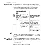
You can also execute the
reset
command in user view to clear statistics on LACP
ports.
Link Aggregation
Configuration
Example
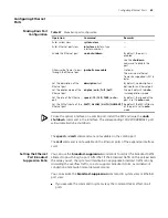
Network requirements
■
Switch A connects to Switch B with three ports GigabitEthernet1/0/1 to
GigabitEthernet1/0/3. It is required that incoming/outgoing load between the two
switch can be shared among the three ports.
■
Adopt three different aggregation modes to implement link aggregation on the
three ports between switch A and B.
Network diagram
Figure 26
Network diagram for link aggregation configuration
Configuration procedure
The following only lists the configuration on Switch A; you must perform the similar
configuration on Switch B to implement link aggregation.
1
Adopting manual aggregation mode
a
Create manual aggregation group 1.
<S4200G>
system-view
[4200G]
link-aggregation group 1 mode manual
b
Add ports GigabitEthernet1/0/1 through GigabitEthernet1/0/3 to aggregation
group 1.
[4200G]
interface GigabitEthernet1/0/1
[4200G-GigabitEthernet1/0/1]
port link-aggregation group 1
[4200G-GigabitEthernet1/0/1]
interface GigabitEthernet1/0/2
[4200G-GigabitEthernet1/0/2]
port link-aggregation group 1
[4200G-GigabitEthernet1/0/2]
interface GigabitEthernet1/0/3
[4200G-GigabitEthernet1/0/3]
port link-aggregation group 1
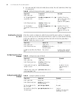
Table 62
Display and maintain link aggregation information
Operation
Command
Display summary information of all
aggregation groups
display link-aggregation summary
Display detailed information of a
specified aggregation group or all
aggregation groups
display link-aggregation verbose
[
agg-id
]
Display link aggregation details of a
specified port or port range
display link-aggregation interface
interface-type
interface-number
[
to
interface-type interface-number
]
Clear LACP statistics on specified
port(s) or all ports
reset lacp statistics
[
interface
interface-type
interface-number
[
to
interface-type
interface-number ]
]
Switch A
Switch B
Link aggregation
Summary of Contents for 4200G 12-Port
Page 10: ...8 CONTENTS...
Page 14: ...4 ABOUT THIS GUIDE...
Page 46: ...32 CHAPTER 5 LOGGING IN THROUGH WEB BASED NETWORK MANAGEMENT SYSTEM...
Page 48: ...34 CHAPTER 6 LOGGING IN THROUGH NMS...
Page 60: ...46 CHAPTER 9 VLAN CONFIGURATION...
Page 64: ...50 CHAPTER 10 MANAGEMENT VLAN CONFIGURATION...
Page 80: ...66 CHAPTER 13 GVRP CONFIGURATION...
Page 98: ...84 CHAPTER 15 LINK AGGREGATION CONFIGURATION...
Page 112: ...98 CHAPTER 18 MAC ADDRESS TABLE MANAGEMENT...
Page 126: ...112 CHAPTER 19 LOGGING IN THROUGH TELNET...
Page 162: ...148 CHAPTER 20 MSTP CONFIGURATION...
Page 274: ...260 CHAPTER 29 IGMP SNOOPING CONFIGURATION...
Page 276: ...262 CHAPTER 30 ROUTING PORT JOIN TO MULTICAST GROUP CONFIGURATION...
Page 298: ...284 CHAPTER 33 SNMP CONFIGURATION...
Page 304: ...290 CHAPTER 34 RMON CONFIGURATION...
Page 338: ...324 CHAPTER 36 SSH TERMINAL SERVICES...
Page 356: ...342 CHAPTER 38 FTP AND TFTP CONFIGURATION...
Page 365: ...Information Center Configuration Example 351 S4200G terminal logging...
Page 366: ...352 CHAPTER 39 INFORMATION CENTER...
Page 378: ...364 CHAPTER 40 BOOTROM AND HOST SOFTWARE LOADING...
Page 384: ...370 CHAPTER 41 Basic System Configuration and Debugging...
Page 388: ...374 CHAPTER 43 NETWORK CONNECTIVITY TEST...
Page 406: ...392 CHAPTER 45 CONFIGURATION OF NEWLY ADDED CLUSTER FUNCTIONS...


