


238
C
HAPTER
28: C
ONFIGURATION
FOR
M
IRRORING
F
EATURES
■
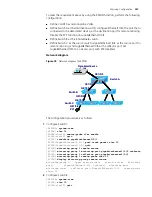
Intermediate switch: the switch between the source and the destination switch on
the network.
■
Destination switch: the switch to which the destination port for remote mirroring
belongs.
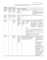
Table 206 describes how the ports on various switches are involved in the mirroring
operation.
To implement remote port management, you need to define a special VLAN, called
Remote-probe VLAN, on all the three types of switches. All mirrored packets will be
transferred to the mirrored ports of the destination switch from the source switch
using this VLAN. Thus, the destination switch can monitor the port packets sent from
the remote ports of the source switch. Remote-probe VLAN has the following
features:
■
The ports connecting the devices and in remote-probe VLAN must be of trunk
type.
■
The default VLAN, management VLAN, and super VLAN cannot be configured as
remote-probe VLAN.
CAUTION:
You are not recommended to perform any of the following operations on
the remote-probe VLAN:
Configuring a source port to the remote-probe VLAN that is used by the local
mirroring group
Configuring a Layer 3 interface
Running other protocol packets, or bearing other service packets;
Using remote-probe VLAN as a special type of VLAN, such as sub VLAN, voice VLAN
or protocol VLAN
Table 206
Ports involved in the mirroring operation
Switch
Ports involved
Function
Source switch
Source port
Port to be mirrored; copy user data packets to the
specified reflector port through local port
mirroring. There can be more than one source
port.
Reflector port
Receive user data packets that are mirrored on a
local port.
Trunk port
Send mirrored packets to the intermediate switch
or the destination switch.
Intermediate
switch
Trunk port
Send mirrored packets to the destination switch.
Two Trunk ports are necessary for the intermediate
switch to be connected to devices that are
connected to the source switch and the destination
switch.
Destination switch Trunk port
Receive remote mirrored packets.
Destination port
Monitor remote mirrored packets
Summary of Contents for 4200G 12-Port
Page 10: ...8 CONTENTS...
Page 14: ...4 ABOUT THIS GUIDE...
Page 46: ...32 CHAPTER 5 LOGGING IN THROUGH WEB BASED NETWORK MANAGEMENT SYSTEM...
Page 48: ...34 CHAPTER 6 LOGGING IN THROUGH NMS...
Page 60: ...46 CHAPTER 9 VLAN CONFIGURATION...
Page 64: ...50 CHAPTER 10 MANAGEMENT VLAN CONFIGURATION...
Page 80: ...66 CHAPTER 13 GVRP CONFIGURATION...
Page 98: ...84 CHAPTER 15 LINK AGGREGATION CONFIGURATION...
Page 112: ...98 CHAPTER 18 MAC ADDRESS TABLE MANAGEMENT...
Page 126: ...112 CHAPTER 19 LOGGING IN THROUGH TELNET...
Page 162: ...148 CHAPTER 20 MSTP CONFIGURATION...
Page 274: ...260 CHAPTER 29 IGMP SNOOPING CONFIGURATION...
Page 276: ...262 CHAPTER 30 ROUTING PORT JOIN TO MULTICAST GROUP CONFIGURATION...
Page 298: ...284 CHAPTER 33 SNMP CONFIGURATION...
Page 304: ...290 CHAPTER 34 RMON CONFIGURATION...
Page 338: ...324 CHAPTER 36 SSH TERMINAL SERVICES...
Page 356: ...342 CHAPTER 38 FTP AND TFTP CONFIGURATION...
Page 365: ...Information Center Configuration Example 351 S4200G terminal logging...
Page 366: ...352 CHAPTER 39 INFORMATION CENTER...
Page 378: ...364 CHAPTER 40 BOOTROM AND HOST SOFTWARE LOADING...
Page 384: ...370 CHAPTER 41 Basic System Configuration and Debugging...
Page 388: ...374 CHAPTER 43 NETWORK CONNECTIVITY TEST...
Page 406: ...392 CHAPTER 45 CONFIGURATION OF NEWLY ADDED CLUSTER FUNCTIONS...


