background image

192 

C

HAPTER

 24: C

ENTRALIZED

 MAC A

DDRESS

 A

UTHENTICATION

 C

ONFIGURATION

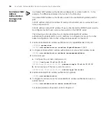
Configuring the ISP Domain for MAC Address Authentication Users

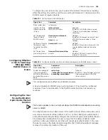
Configuring the Timers Used in Centralized MAC Address Authentication

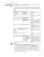
The configuration of the maximum number of learned MAC addresses (refer to the 

mac-address max-mac-count

 command) is unavailable for the ports with 

centralized MAC address authentication enabled. Similarly, the centralized MAC 
address authentication is unavailable for the ports with the maximum number of 
learned MAC addresses configured.

Enabling Centralized

MAC Address

Authentication Globally

and for a Port

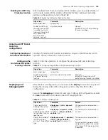
Centralized MAC address authentication configuration takes effect on a port only 
after you enable centralized MAC address authentication globally.

Configuring Centralized

MAC Address

Authentication Mode

Configuring a User

Name and Password to

be used in Fixed Mode

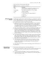
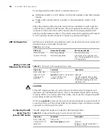
When the fixed mode is adopted, you need to configure the user names and 
passwords.

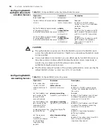
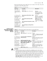
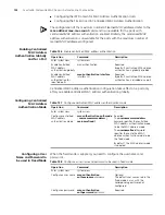
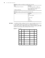
Table 156   

Enable centralized MAC address authentication

Operation

Command

Description

Enter system view

system-view

Enable centralized 
MAC address 
authentication globally

mac-authentication

Required
By default, centralized MAC address 
authentication is globally disabled.

Enable centralized 
MAC address 
authentication for 
specified ports

mac-authentication


interface


interface-list

Required
By default, centralized MAC address 
authentication is disabled on a port.

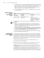
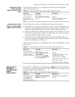
Table 157   

Configure centralized MAC address authentication mode

Operation

Command

Description

Enter system view

system-view

Configure centralized 
MAC address 
authentication mode

mac-authentication authmode 

{

usernameasmacaddress

 | 

usernamefixed }

Required
The 

usernameasmacaddress


keyword specifies the centralized 
MAC address authentication mode 
to be the MAC address mode.

The 

usernamefixed

 keyword 

specifies the centralized MAC 
address authentication mode to be 
the fixed mode.

By default, the MAC address mode 
is adopted.

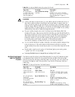
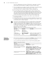
Table 158   

Configure a user name and password to be used in fixed mode

Operation

Command

Description

Enter system view

system-view

Configure a user name

mac-authentication


authusername 

username

Optional
The default user name used in the 
fixed mode is mac, with the 
corresponding password not 
configured.

Configure a password

mac-authentication 
authpassword

 password

Required

Summary of Contents for 4200G 12-Port

Page 1: ...3Com Switch 4200G Family Configuration Guide 4200G 12 Port 3CR17660 91 4200G 24 Port 3CR17661 91 4200G 48 Port 3CR17662 91 www 3Com com Part Number 10014915 Rev AD Published May 2007...

Page 2: ...227 7015 Nov 1995 or FAR 52 227 14 June 1987 whichever is applicable You agree not to remove or deface any portion of any legend provided on any licensed program or documentation contained in or deli...

Page 3: ...hentication Mode Being None 15 Console Port Login Configuration with Authentication Mode Being Password 18 Console Port Login Configuration with Authentication Mode Being Scheme 21 4 LOGGING IN USING...

Page 4: ...ent Configuration 53 12 VOICE VLAN CONFIGURATION Voice VLAN Configuration 55 Voice VLAN Configuration 57 Voice VLAN Displaying and Debugging 59 Voice VLAN Configuration Example 59 13 GVRP CONFIGURATIO...

Page 5: ...02 Telnet Configuration with Authentication Mode Being Scheme 105 Telnet Connection Establishment 109 20 MSTP CONFIGURATION MSTP Overview 113 Root Bridge Configuration 118 Leaf Node Configuration 131...

Page 6: ...Example 194 25 ARP CONFIGURATION Introduction to ARP 195 Introduction to Gratuitous ARP 197 ARP Configuration 198 Gratuitous ARP Packet Learning configuration 199 Displaying and Debugging ARP 199 26 A...

Page 7: ...CONFIGURATION Introduction 263 Configuring a Multicast MAC Address Entry 263 Displaying Multicast MAC Address Configuration 264 32 CLUSTER CONFIGURATION Cluster Overview 265 Management Device Configu...

Page 8: ...TFTP Configuration 339 39 INFORMATION CENTER Information Center Overview 343 Information Center Configuration 345 Displaying and Debugging Information Center 350 Information Center Configuration Examp...

Page 9: ...n Example for Newly Added Cluster Functions 390 46 DHCP RELAY CONFIGURATION Introduction to DHCP Relay 393 DHCP Relay Configuration 395 Option 82 Supporting Configuration 397 DHCP Relay Displaying 399...

Page 10: ...8 CONTENTS...

Page 11: ...tion information to create Voice VLAN GVRP Configuration Details GARP VLAN Registration Protocol configuration Port Operation Details how to configure Ethernet ports Link Aggregation Details how to ag...

Page 12: ...s how to how to configure a basic system IP Performance Configuration Details how to configure routing protocols Network Protocol Operation Details how to configure network protocols Network Connectiv...

Page 13: ...here and press Return or Enter when you are ready to enter the command Example in the command super level a value in the range 0 to 3 must be entered in the position indicated by level x y Alternativ...

Page 14: ...4 ABOUT THIS GUIDE...

Page 15: ...the ping tracert and language mode commands are at this level Monitor level Commands at this level are mainly used to maintain the system and diagnose service problems and cannot be saved to configur...

Page 16: ...And by executing the system view command you can enter system view where you can enter other views by executing the corresponding commands The following CLI views are provided User view Table 1 Set a...

Page 17: ...Prompt example Enter method Quit method User view Display operation status and statistical information S4200G Enter user view once logging into the switch Execute the quit command in user view to log...

Page 18: ...1 Execute the local user user1 command in system view Execute the quit command to return to system view Execute the return command to return to user view User interface view Configure user interface p...

Page 19: ...to user view Advanced ACL view Define rules for an advanced ACL ACLs with their IDs ranging from 3000 to 3999 are advanced ACLs 4200G acl adv 3000 Execute the acl number 3000 command in system view E...

Page 20: ...rief descriptions The following takes the clock command as an example S4200G clock datetime Specify the time and date summer time Configure summer time timezone Configure time zone Enter a command a s...

Page 21: ...ages If the command you enter passes the syntax check it will be successfully executed otherwise an error message will appear Table 7 lists the common error messages Table 5 Displaying related operati...

Page 22: ...the cursor one character to the left The left arrow key or Ctrl B Move the cursor one character to the left The right arrow key or Ctrl F Move the cursor one character to the right The up arrow key or...

Page 23: ...ough this port User Interface Number Two kinds of user interface index exist absolute user interface index and relative user interface index 1 The absolute user interface indexes are as follows AUX us...

Page 24: ...ecified user interface send all number type number Optional Execute this command in user view Disconnect a specified user interface free user interface type number Optional Execute this command in use...

Page 25: ...tting up the Connection to the Console Port Connect the serial port of your PC terminal to the Console port of the switch as shown in Figure 1 Figure 1 Diagram for setting the connection to the Consol...

Page 26: ...12 CHAPTER 3 LOGGING IN THROUGH THE CONSOLE PORT Figure 2 Create a connection Figure 3 Specify the port used to establish the connection...

Page 27: ...12 lists the common configuration of Console port login Table 12 Common configuration of Console port login Configuration Description Console port configuration Baud rate Optional The default baud rat...

Page 28: ...the screen can contain Optional By default the screen can contain up to 24 lines Set history command buffer size Optional By default the history command buffer can contain up to 10 commands Set the ti...

Page 29: ...password of a local user are configured on the switch The user name and password of a remote user are configured on the RADIUS server Refer to user manual of RADIUS server for more Manage AUX users Se...

Page 30: ...rminal services are available in all user interfaces Set the maximum number of lines the screen can contain screen length screen length Optional By default the screen can contain up to 24 lines You ca...

Page 31: ...port is 19 200 bps The screen can contain up to 30 lines The history command buffer can contain up to 20 commands The timeout time of the AUX user interface is 6 minutes Network diagram Figure 5 Netw...

Page 32: ...uration with the authentication mode being password Operation Command Description Enter system view system view Enter AUX user interface view user interface aux 0 Configure to authenticate users using...

Page 33: ...ngth Optional By default the screen can contain up to 24 lines You can use the screen length 0 command to disable the function to display information in pages Set history command buffer size history c...

Page 34: ...mode password 4 Set the local password to 123456 in plain text 4200G ui aux0 set authentication password simple 123456 5 Specify commands of level 2 are available to users logging into the AUX user i...

Page 35: ...Perform AAA RADIUS configuration on the switch Refer to AAA RADIUS Configuration for more Configure the user name and password accordingly on the AAA server Refer to the user manual of AAA server Spe...

Page 36: ...ional By default terminal services are available in all user interfaces Set the maximum number of lines the screen can contain screen length screen length Optional By default the screen can contain up...

Page 37: ...ort is 19 200 bps The screen can contain up to 30 lines The history command buffer can store up to 20 commands The timeout time of the AUX user interface is 6 minutes Table 19 Determine the command le...

Page 38: ...user interface aux 0 6 Configure to authenticate users logging in through the Console port in the scheme mode 4200G ui aux0 authentication mode scheme 7 Specify commands of level 2 are available to us...

Page 39: ...e the factory settings ATS0 1 Configure to answer automatically after the first ring AT D Ignore DTR signal AT K0 Disable flow control AT R1 Ignore RTS signal AT S0 Set DSR to high level by force ATEQ...

Page 40: ...mode is password Configuration on switch when the authentication mode is scheme Refer to Configuration on switch when the authentication mode is scheme Modem Connection Establishment 1 Configure the u...

Page 41: ...elephone number to call the modem directly connected to the switch as shown in Figure 9 and Figure 10 Note that you need to set the telephone number to that of the modem directly connected to the swit...

Page 42: ...rect the prompt such as S4200G appears You can then configure or manage the switch You can also enter the character at anytime for help If you perform no AUX user related configuration on the switch t...

Page 43: ...ole port To log into a switch through the Console port you need to connect the serial port of your PC or terminal to the Console port of the switch using a configuration cable as shown in Figure 11 Fi...

Page 44: ...of the switch S4200G system a Enter management VLAN interface view 4200G interface vlan interface 1 b Remove the existing IP address of the management VLAN interface 4200G VLAN interface1 undo ip add...

Page 45: ...http 10 153 17 82 Make sure the route between the Web based network management terminal and the switch is available 5 When the login interface shown in Figure 14 appears enter the user name and the p...

Page 46: ...32 CHAPTER 5 LOGGING IN THROUGH WEB BASED NETWORK MANAGEMENT SYSTEM...

Page 47: ...to perform related configuration on both the NMS and the switch Connection Establishment Using NMS Figure 15 Network diagram for logging in through an NMS Table 23 Requirements for logging into a swit...

Page 48: ...34 CHAPTER 6 LOGGING IN THROUGH NMS...

Page 49: ...ddresses Through basic ACLs Controlling Network Management Users by Source IP Addresses WEB By source IP addresses Through basic ACLs Controlling Web Users by Source IP Address Disconnect Web users by...

Page 50: ...3 deny source any 4200G acl basic 2000 quit 2 Apply the ACL 4200G user interface vty 0 4 4200G ui vty0 4 acl 2000 inbound Table 26 Define an advanced ACL Operation Command Description Enter system vie...

Page 51: ...able 27 Control network management users by source IP addresses Operation Command Description Enter system view system view Create a basic ACL or enter basic ACL view acl number acl number match order...

Page 52: ...fy ACLs in the two operations the switch will filter network management users by both SNMP group name and SNMP user name Configuration Example Network requirements Only SNMP users sourced from the IP...

Page 53: ...y force using the related command Configuration Example Network requirements Only the users sourced from the IP address of 10 110 100 46 are permitted to access the switch Network diagram Figure 18 Ne...

Page 54: ...system view 4200G acl number 2030 match order config 4200G acl basic 2030 rule 1 permit source 10 110 100 46 0 4200G acl basic 2030 rule 2 deny source any 2 Apply the ACL to only permit the Web users...

Page 55: ...ts with the character The sections are listed in this order system configuration section physical port configuration section logical interface configuration section routing protocol configuration sect...

Page 56: ...isplay saved configuration unit unit id by linenum Optional This command can be executed in any view Check the current configuration display current configuration configuration configuration type inte...

Page 57: ...is hosts in a VLAN can belong to different physical network segment VLAN enjoys the following advantages 1 Broadcasts are confined to VLANs This decreases bandwidth utilization and improves network pe...

Page 58: ...command in any view to view the running of the VLAN configuration and to verify the effect of the configuration Table 31 Basic VLAN configuration Operation Command Description Enter system view syste...

Page 59: ...iption string of VLAN 2 to be home 4200G vlan2 description home 4 Add GigabitEthernet1 0 1 and GigabitEthernet1 0 2 ports to VLAN 2 4200G vlan2 port GigabitEthernet1 0 1 GigabitEthernet1 0 2 5 Create...

Page 60: ...46 CHAPTER 9 VLAN CONFIGURATION...

Page 61: ...g commands and then apply for another IP address through BOOTP using the ip address bootp alloc command the former IP address will be removed and the final IP address of the VLAN interface is the one...

Page 62: ...t VLAN Operation Command Description Enter system view system view Configure a specified VLAN to be the management VLAN management vlan vlan id Required By default VLAN 1 operates as the management VL...

Page 63: ...erface vlan id Optional You can execute the display commands in any view Display the information about a management VLAN interface display interface vlan interface vlan id Display summary information...

Page 64: ...50 CHAPTER 10 MANAGEMENT VLAN CONFIGURATION...

Page 65: ...t configuration protocol DHCP is developed to meet these requirements It adopts the client server model The DHCP client requests configuration information from the DHCP server dynamically and the DHCP...

Page 66: ...rvers and broadcasts a DHCP_Request packet to each DHCP server The packet contains the IP address carried by the DHCP_Offer packet Acknowledgement Upon receiving the DHCP_Request packet the DHCP serve...

Page 67: ...res The DHCP server in turn responds with a DHCP_ACK packet to notify the DHCP client of the new lease if the IP address is still available The DHCP clients implemented by the switches support this le...

Page 68: ...face 10 4 Configure the management VLAN interface to obtain an IP address through DHCP 4200GA Vlan interface10 ip address dhcp alloc 4200GA Vlan interface10 quit 5 Configure a default route 4200GA ip...

Page 69: ...atic mode and manual mode You can configure the operation mode for a voice VLAN according to data stream passing through the ports of the voice VLAN When a voice VLAN operates in the automatic mode th...

Page 70: ...oice VLAN And the access port permits the packets of the default VLAN Hybrid Supported Make sure the default VLAN of the port exists and is in the list of the tagged VLANs whose packets are permitted...

Page 71: ...Quit to system view quit Set an OUI address that can be identified by the voice VLAN voice vlan mac address oui mask oui mask description string Optional If you do not set the OUI address the default...

Page 72: ...quired Add the port to the VLAN port port type port num Trunk or hybrid port Enter port view interface interface type interface num Add the port to the voice VLAN port trunk permit vlan vlan id port h...

Page 73: ...igabitEthernet1 0 3 port trunk pvid vlan 6 3 Enable the voice VLAN function for the port and configure the port to operate in automatic mode 4200G GigabitEthernet1 0 1 voice vlan enable 4200G GigabitE...

Page 74: ...3 voice vlan enable 4200G GigabitEthernet1 0 3 undo voice vlan mode auto 4200G GigabitEthernet1 0 3 quit 4 Specify an OUI address 4200G voice vlan mac address 0011 2200 0000 mask ffff ff00 0000 descr...

Page 75: ...rming important functions for GARP fall into three types Join Leave and LeaveAll When a GARP entity expects other switches to register certain attribute information of its own it sends out a Join mess...

Page 76: ...P cannot learn dynamic VLAN through this port and the dynamic VLANs learned through other ports on this switch cannot be pronounced through this port Forbidden In this mode all the VLANs except VLAN 1...

Page 77: ...three parts Attribute Length Attribute Event and Attribute Value Each LeaveAll attribute consists of two parts Attribute Length and LeaveAll Event Attribute Length The length of the attribute 2 to 255...

Page 78: ...o a different type Configure GVRP port registration mode gvrp registration normal fixed forbidden Optional You can choose one of the three modes By default GVRP port registration mode is normal Table...

Page 79: ...type trunk 4200G GigabitEthernet1 0 2 port trunk permit vlan all c Enable GVRP on the trunk port 4200G GigabitEthernet1 0 2 gvrp Displaying and Maintaining GVRP After the above configuration you can...

Page 80: ...66 CHAPTER 13 GVRP CONFIGURATION...

Page 81: ...sed to connect user PCs Trunk A trunk port can belong to more than one VLAN It can receive send packets from to multiple VLANs and is generally used to connect another switch Hybrid A hybrid port can...

Page 82: ...that the port shall be added to an existing VLAN Table 46 Processing of incoming outgoing packet Port type Processing of an incoming packet Processing of an outgoing packet If the packet does not carr...

Page 83: ...ervices You can execute the broadcast suppression command in system view or Ethernet port view If you execute the command in system view the command takes effect on all ports Table 47 Make basic port...

Page 84: ...ratio pps max pps By default the ratio is 100 that is the system does not suppress broadcast traffic on the port Table 49 Enable flow control on a port Operation Command Remarks Enter system view syst...

Page 85: ...configuration of the source port will be copied to all ports in the aggregation group Add the current hybrid port into the specified VLAN port hybrid vlan vlan id list tagged untagged Optional For a...

Page 86: ...the Ethernet port to run loopback test to check if it operates normally The port running loopback test cannot forward data packets normally The loopback test terminates automatically after a specific...

Page 87: ...ch A is connected to Switch B through trunk port GigabitEthernet1 0 1 Configure the default VLAN ID for the trunk port as 100 Allow the packets of VLAN 2 VLAN 6 through VLAN 50 and VLAN 100 to pass th...

Page 88: ...00 to pass the port 4200G GigabitEthernet1 0 1 port link type trunk 4200G GigabitEthernet1 0 1 port trunk permit vlan 2 6 to 50 100 3 Create VLAN 100 4200G vlan 100 4 Configure the default VLAN ID of...

Page 89: ...tribute configuration including port rate duplex mode and link type Trunk Hybrid or Access Introduction to LACP The purpose of link aggregation control protocol LACP is to implement dynamic link aggre...

Page 90: ...hat is the ports take most precedence over other ports to selected state and others to unselected state Port precedence descends in the following order full duplex high speed full duplex low speed hal...

Page 91: ...ts take most precedence over other ports to selected state and others to unselected state Port precedence descends in the following order full duplex high speed full duplex low speed half duplex high...

Page 92: ...the latter following the former between the two parties First compare the two system priorities then the two system MAC addresses if the system priorities are equal The device with smaller device ID w...

Page 93: ...higher speed if resources were allocated to it has higher priority than the other one If the two groups can gain the same speed the one with smaller master port number has higher priority than the ot...

Page 94: ...egation group after that the system will re aggregate the original member ports in the group to form one or more dynamic aggregation groups You can manually add remove a port to from a static aggregat...

Page 95: ...execute the display commands in any view to display link aggregation conditions and verify your configuration Add the port to the aggregation group port link aggregation group agg id Required Enable...

Page 96: ...anual b Add ports GigabitEthernet1 0 1 through GigabitEthernet1 0 3 to aggregation group 1 4200G interface GigabitEthernet1 0 1 4200G GigabitEthernet1 0 1 port link aggregation group 1 4200G GigabitEt...

Page 97: ...et1 0 2 interface GigabitEthernet1 0 3 4200G GigabitEthernet1 0 3 port link aggregation group 1 3 Adopting dynamic LACP aggregation mode a Enable LACP on ports GigabitEthernet1 0 1 through GigabitEthe...

Page 98: ...84 CHAPTER 15 LINK AGGREGATION CONFIGURATION...

Page 99: ...ons to add an Ethernet ports to an isolation group Displaying Port Isolation After the above configuration you can execute the display command in any view to display the information about the Ethernet...

Page 100: ...gabitEthernet1 0 2 quit 4200G interface GigabitEthernet1 0 3 4200G GigabitEthernet1 0 3 port isolate 4200G GigabitEthernet1 0 3 quit 4200G interface GigabitEthernet1 0 4 4200G GigabitEthernet1 0 4 por...

Page 101: ...due to illegal intrusion improper manner of logging on and off are transmitted the switch will send Trap message to help the network administrators monitor and control such actions 4 Binding of MAC a...

Page 102: ...erformed simultaneously If both kinds of authentication succeed the userlogin secure mode takes precedence over the mac authentication mode mac else userlogin In this mode first the MAC based authenti...

Page 103: ...ort in the same VLAN Using this feature you can bind a MAC address with a port in the same VLAN Set the security mode of a port port security port mode mode Required Users can choose the optimal mode...

Page 104: ...be configured with mac address max mac count count Displaying Port Security To display port security related information after the above configuration enter the following command in any view Table 67...

Page 105: ...the port mode to MAC authentication 4200G GigabitEthernet1 0 1 port security port mode mac authentication 5 Set the maximum number of MAC addresses accommodate by the port to 80 4200G GigabitEthernet...

Page 106: ...ble the sending of intrusion trap messages 4200G port security trap intrusion 10 Bind the MAC and IP addresses of PC1 to GigabitEthernet1 0 1 port 4200G am user bind mac address 00e0 fc00 4200G ip add...

Page 107: ...dress entry Also known as permanent MAC address entry This type of MAC address entries are added removed manually and can not age out by themselves Using static MAC address entries can reduce broadcas...

Page 108: ...le After that the switch can directly forward other packets destined for the same network device by the newly added MAC address entry Among the three types of packets unicast packets multicast packets...

Page 109: ...type of MAC address entries such as dynamic or static MAC address entries Setting the Maximum Number of MAC Addresses a Port can Learn A MAC address table too big in size may decrease the forwarding p...

Page 110: ...t1 0 2 port assuming that the port belongs to VLAN 1 with the MAC address of 00e0 fc35 dc71 Network diagram Figure 29 Network diagram for MAC address table configuration Table 72 Disable MAC address l...

Page 111: ...ress timer aging 500 4 Display the information about the MAC address table 4200G display mac address interface GigabitEthernet1 0 2 MAC ADDR VLAN ID STATE PORT INDEX AGING TIME 00 e0 fc 35 dc 71 1 Sta...

Page 112: ...98 CHAPTER 18 MAC ADDRESS TABLE MANAGEMENT...

Page 113: ...gure the command level available to users logging into the VTY user interface Optional By default commands of level 0 is available to users logging into a VTY user interface Configure the protocols th...

Page 114: ...lnet configuration Description Table 77 Telnet configuration with the authentication mode being none Operation Command Description Enter system view system view Enter one or more VTY user interface vi...

Page 115: ...size history command max size value Optional The default history command buffer size is 10 That is a history command buffer can store up to 10 commands by default Set the timeout time of the VTY user...

Page 116: ...ol is supported 4200G ui vty0 protocol inbound telnet 6 Set the maximum number of lines the screen can contain to 30 4200G ui vty0 screen length 30 7 Set the maximum number of commands the history com...

Page 117: ...nes the screen can contain screen length screen length Optional By default the screen can contain up to 24 lines You can use the screen length 0 command to disable the function to display information...

Page 118: ...cedure 1 Enter system view S4200G system view 2 Enter VTY 0 user interface view 4200G user interface vty 0 3 Configure to authenticate users logging into VTY 0 using the local password 4200G ui vty0 a...

Page 119: ...ocal radius scheme radius scheme name local none Quit to system view quit Create a local user and enter local user view local user user name No local user exists by default Set the authentication pass...

Page 120: ...and buffer size is 10 That is a history command buffer can store up to 10 commands by default Set the timeout time for the user interface idle timeout minutes seconds Optional The default timeout time...

Page 121: ...ed and the service type command specifies the available command level Determined by the service type command VTY users that are authenticated in the RSA mode of SSH The user privilege level level comm...

Page 122: ...lines The history command buffer can store up to 20 commands The timeout time of VTY 0 is 6 minutes Network diagram Figure 32 Network diagram for Telnet configuration with the authentication mode bei...

Page 123: ...nd execute the ip address command Following are procedures to establish a Telnet connection to a switch 1 Configure the user name and password for Telnet on the switch Refer to Telnet Configuration wi...

Page 124: ...rrent Switch You can Telnet to another switch from the current switch In this case the current switch operates as the client and the other operates as the server If the interconnected Ethernet ports o...

Page 125: ...rd is correct the CLI prompt such as S4200G appears If all VTY user interfaces of the switch are in use you will fail to establish the connection and receive the message that says All user interfaces...

Page 126: ...112 CHAPTER 19 LOGGING IN THROUGH TELNET...

Page 127: ...alances the forwarding loads of different VLANs MSTP is compatible with both STP and RSTP It overcomes the drawback of STP and RSTP It not only enables spanning trees to converge rapidly but also enab...

Page 128: ...mapped to spanning tree instance 1 VLAN 2 is mapped to spanning tree instance 2 and other VLANs are mapped to CIST the same MSTP revision level not shown in Figure 36 MSTI A multiple spanning tree in...

Page 129: ...ent region roots In region D0 shown in Figure 36 the region root of MSTI 1 is switch B and the region root of MSTI 2 is switch C Common root bridge The common root bridge is the root of the CIST The c...

Page 130: ...is a region edge port and it is a master port in the CIST So it is a master port in all MSTIs in the region Figure 37 Port roles Port states Ports can be in the following three states Forwarding stat...

Page 131: ...ng a configuration BPDU on one of its ports from another switch If the priority of the configuration BPDU is lower than that of the configuration BPDU of the port itself the switch discards the BPDU a...

Page 132: ...ith both STP and RSTP That is switches with MSTP employed can recognize the protocol packets of STP and RSTP and use them to generate spanning trees In addition to the basic MSTP functions S4200G seri...

Page 133: ...itch in each spanning tree instance is determined Network diameter configuration Optional The default is recommended Network Diameter Configuration MSTP time related configuration Optional The default...

Page 134: ...ration 4200G mst region region name info 4200G mst region instance 1 vlan 2 to 10 4200G mst region instance 2 vlan 20 to 30 4200G mst region revision level 1 4200G mst region active region configurati...

Page 135: ...e root bridge and the secondary root bridge simultaneously When the root bridge fails or is turned off the secondary root bridge becomes the root bridge if no new root bridge is configured If you conf...

Page 136: ...t bridge by set a higher bridge priority for the switch Note that a smaller bridge priority value indicates a higher bridge priority A MSTP enabled switch can have different bridge priorities in diffe...

Page 137: ...n a MST region the value of the remaining hops field in the configuration BPDU is decreased by 1 every time the configuration BPDU passes a switch Such a mechanism disables the switches that are beyon...

Page 138: ...tion You can configure three MSTP time related parameters for a switch Forward delay Hello time and Max age The Forward delay parameter sets the delay of state transition Link problems occurred in a n...

Page 139: ...ended As for the Max age parameter if it is too small network congestions may be falsely regarded as link problems which results in spanning trees being frequently regenerated If it is too large link...

Page 140: ...rees may be regenerated even in a steady network if an upstream switch continues to be busy You can configure the timeout time factor to a larger number to avoid this Normally the timeout time can be...

Page 141: ...neither directly connects to other switches nor indirectly connects to other switches through network segments After a port is configured as an edge port rapid transition is applicable to the port Tha...

Page 142: ...rnet1 0 1 stp edged port enable Point to point Link Related Configuration A point to point link directly connects two switches If the roles of the two ports at the two ends of a point to point link me...

Page 143: ...int to point links stp interface interface list point to point force true force false auto Required The auto keyword is adopted by default The force true keyword specifies that the links connected to...

Page 144: ...view system view Enable MSTP stp enable Required MSTP is disabled by default Disable MSTP on specified ports stp interface interface list disable Optional By default MSTP is enabled on all ports after...

Page 145: ...on Configuration MSTP Operation Mode Configuration Refer to MSTP Operation Mode Configuration Timeout Time Factor Configuration Refer to Timeout Time Factor Configuration Table 102 Leaf node configura...

Page 146: ...gacy Adopts the standard defined by 3Com to calculate the default path costs of ports Table 103 Specify the standard for calculating path costs Operation Command Description Enter system view system v...

Page 147: ...tance 1 to be 2 000 Configure in system view S4200G system view System View return to User View with Ctrl Z 4200G stp interface GigabitEthernet1 0 1 instance 1 cost 2000 10 Gbps Full duplex Aggregated...

Page 148: ...al to become the root port than another port with lower priority A port on a MSTP enabled switch can have different port priorities and play different roles in different spanning tree instances This e...

Page 149: ...w with Ctrl Z 4200G interface GigabitEthernet1 0 1 4200G GigabitEthernet1 0 1 stp instance 1 port priority 16 Point to point Link Related Configuration Refer to Point to point Link Related Configurati...

Page 150: ...ces operating on the access layer directly connect to terminals such as PCs or file servers These ports are usually configured as edge ports to achieve rapid transition But they resume non edge ports...

Page 151: ...use of network congestions and link failures If a switch does not receive BPDUs from the upstream switch for certain period the switch selects a new root port the original root port becomes a designat...

Page 152: ...t1 0 1 stp root protection Loop Prevention Configuration You can configure the loop prevention function in the following two ways Table 111 Enable the BPDU protection function Operation Command Descri...

Page 153: ...rks through which spanning trees can be generated across these user networks and are independent of those of the operator s network Table 114 Enable the loop prevention function on specified ports in...

Page 154: ...ks are trunk links As the VLAN VPN function is unavailable on ports with 802 1x GVRP GMRP STP or NTDP employed the BPDU Tunnel function is not applicable to these ports Packet ingress egress device N...

Page 155: ...itch In this way the S4200G series switches can interwork with the partners switches in the same MST region Digest Snooping Configuration Configure the digest snooping feature on a switch to enable it...

Page 156: ...tream switch A RSTP upstream switch does not send agreement packets to the downstream switch Figure 39 and Figure 40 illustrate the RSTP and MSTP rapid transition mechanisms Figure 39 The RSTP rapid t...

Page 157: ...ts those operating as the root ports will then send agreement packets to their upstream ports after they receive proposal packets from the upstream designated ports instead of waiting for agreement pa...

Page 158: ...erface interface type interface number no agreement check Required By default the rapid transition feature is disabled on a port Table 120 Configure the rapid transition feature in Ethernet port view...

Page 159: ...es of spanning tree instance 1 and spanning tree instance 3 respectively Switch C is configured as the root bridge of spanning tree instance 4 Network diagram Figure 42 Network diagram for implementin...

Page 160: ...ion instance 4 vlan 40 4200G mst region revision level 0 c Activate the settings of the MST region 4200G mst region active region configuration d Specify Switch B as the root bridge of spanning tree i...

Page 161: ...0G mst region region name example 4200G mst region instance 1 vlan 10 4200G mst region instance 3 vlan 30 4200G mst region instance 4 vlan 40 4200G mst region revision level 0 c Activate the settings...

Page 162: ...148 CHAPTER 20 MSTP CONFIGURATION...

Page 163: ...otocol over LANs The authenticator system authenticates the supplicant system The authenticator system is usually an 802 1x supported network device such as a S4200G series switch It provides the port...

Page 164: ...ntrolled port When a controlled port is in unauthorized state you can configure it to be a unidirectional port which sends packets to supplicant systems only By default a controlled port is a unidirec...

Page 165: ...ator systems through LANs EAP protocol packets are encapsulated in EAPoL format Figure 45 illustrates the structure of an EAPoL packet Figure 45 The format of an EAPoL packet In an EAPoL packet The PA...

Page 166: ...e Identifier Length and Data fields The Data field differs with the Code field A Success or Failure packet whose format is shown in Figure 47 does not contain the Data field so has the Length field of...

Page 167: ...de normally requires the RADIUS server to support the two newly added fields the EAP message field with a value of 79 and the Message authenticator field with a value of 80 Three authentication ways E...

Page 168: ...g packet EAP Request Identity Handshake response packet EAP Response Identity Logoff Supplicant system Sw itch RADIUS server Start EAP Request Identity EAP Response Identity EAP Request MD5 Challenge...

Page 169: ...m accepted to rejected In EAP relay mode packets are not modified during transmission Therefore if one of the three ways are used that is PEAP EAP TLS or EAP MD5 to authenticate ensure that the authen...

Page 170: ...uthentication server timer This timer sets the server timeout period The switch sends another authentication request packet if the authentication server fails to respond when this timer times out Sup...

Page 171: ...nt It enables a network to operate in the desired way and enables you to manage a network in a easy way It also ensures network security Checking the supplicant system An S4200G series switch checks W...

Page 172: ...you specify to use the RADIUS scheme that is to say the supplicant systems are authenticated by a remote RADIUS server you need to configure the related user names and passwords on the RADIUS server...

Page 173: ...1x Set port access control mode for specified ports dot1x port control authorized force unauthorized force auto interface interface list Optional By default an 802 1x enabled port operates in an auto...

Page 174: ...er or an IE proxy By default the use of multiple network cards proxy server and IE proxy are allowed on 802 1x client If you specify CAMS to disable use of multiple network cards proxy server and IE p...

Page 175: ...ation Command Description Enter system view system view Enable 802 1x client version checking dot1x version check interface interface list Required By default 802 1x client version checking is disable...

Page 176: ...unting fails the connected user has not included the domain name in the username and there is a continuous below 2000 bytes of traffic for over 20 minutes The switch is connected to a server comprisin...

Page 177: ...Network diagram for AAA configuration with 802 1x and RADIUS enabled Configuration procedure Following configuration covers the major AAA RADIUS configuration commands You can refer to AAA RADIUS Ope...

Page 178: ...radius radius1 timer realtime accounting 15 11 Specify to send user names to the RADIUS servers with the domain name truncated Configure to send the user name to the RADIUS server with the domain name...

Page 179: ...Normally an HABP server sends HABP request packets regularly to HABP clients to collect the MAC addresses of the attached switches HABP clients respond to the HABP request packets and forward the HABP...

Page 180: ...ute the display command in any view Table 130 Configure an HABP client Operation Command Description Enter system view system view Enable HABP habp enable Optional HABP is enabled by default And a swi...

Page 181: ...vice Local authentication is fast and requires lower operational cost But the information storage capacity is limited by device hardware Remote authentication Users are authenticated remotely through...

Page 182: ...information interacting protocol in client server structure It can prevent unauthorized access to the network and is commonly used in network environments where both high security and remote user acce...

Page 183: ...r Users Clients Dictionary RADIUS Server 1 The user inputs the user name and password 2 Access Request PC RADIUS Client 3 Access Accept 4 Accounting Request start 5 Accounting Response 7 Accounting Re...

Page 184: ...ure RADIUS uses UDP to transmit messages It ensures the correct message exchange between RADIUS server and client through the following mechanisms timer management retransmission and backup server Fig...

Page 185: ...he total length of the Attribute field in bytes including the Type Length and Value fields The Value field up to 253 bytes contains the information about the attribute Its content and format are deter...

Page 186: ...implementation Figure 57 Part of the RADIUS packet containing extended attribute 13 Framed Compression 35 Login LAT Node 14 Login IP Host 36 Login LAT Group 15 Login Service 37 Framed AppleTalk Link...

Page 187: ...S accounting servers Required Configuring RADIUS Accounting Servers Configure shared keys for RADIUS packets Optional Configuring Shared Keys for RADIUS Packets Configure the maximum number of transmi...

Page 188: ...e attributes of an ISP domain Operation Command Description Enter system view system view Create an ISP domain or enter the view of an existing ISP domain domain isp name Required Activate deactivate...

Page 189: ...you specify a RADIUS scheme the authentication authorization and accounting will be uniformly implemented by the RADIUS server specified in the RADIUS scheme In this way you can specify only one schem...

Page 190: ...ntication authorization and accounting schemes the separate ones will be adopted in precedence RADIUS scheme and local scheme do not support the separation of authentication and authorization Therefor...

Page 191: ...he corresponding VLAN Otherwise the VLAN assignment fails and the user cannot pass the authentication In actual applications to use this feature together with Guest VLAN you should better set port con...

Page 192: ...local user user name Required By default there is no local user in the system Set a password for the specified user password simple cipher password Optional Set the password display mode of all local...

Page 193: ...r and at the same time you should keep the RADIUS service port settings on the switch consistent with those on the RADIUS servers Actually the RADIUS protocol configuration only defines the parameters...

Page 194: ...primary server are 0 0 0 0 and 1812 respectively Set the IP address and port number of the secondary RADIUS authentication authorization server secondary authentication ip address port number Optiona...

Page 195: ...and the port number of the default primary accounting server system are 127 0 0 1 and 1646 Currently RADIUS does not support the accounting of FTP users Configuring Shared Keys for RADIUS Packets The...

Page 196: ...s the time set with the timer quiet command the switch will try to communicate with the primary server again when it receives a RADIUS request If the primary server recovers the switch immediately res...

Page 197: ...are in the active state and the RADIUS servers in the default RADIUS scheme system are in the block state Set the status of the primary RADIUS accounting server state primary accounting block active S...

Page 198: ...out a RADIUS request authentication authorization request or accounting request and waiting for a period of time it should retransmit the packet to ensure that the user can obtain the RADIUS service T...

Page 199: ...his case the user can access the network again only after the CAMS administrator manually removes the online information of the user Table 151 Set the timers of RADIUS server Operation Command Descrip...

Page 200: ...e attribute be sure to configure an appropriate and legal IP address If this attribute is not configured the switch will automatically use the IP address of the VLAN interface as the NAS IP address Di...

Page 201: ...hared key it uses to exchange packets with the switch to expert Set the port number for authentication Add Telnet user names and login passwords The Telnet user name added to the RADIUS server must be...

Page 202: ...0G domain cams 4200G isp cams scheme radius scheme cams A Telnet user logging into the switch by a name in the format of userid cams belongs to the cams domain and will be authenticated according to t...

Page 203: ...tem scheme local A Telnet user logging into the switch with the name telnet system belongs to the system domain and will be authenticated according to the configuration of the system domain 2 Method 2...

Page 204: ...IUS packets cannot be sent to the RADIUS server Possible reasons and solutions The communication links physical link layer between the switch and the RADIUS server is disconnected blocked Take measure...

Page 205: ...address mode a switch sends user MAC addresses detected to the RADIUS serve as both user names and passwords The rest handling procedures are the same as that of 802 1x In fixed mode a switch sends t...

Page 206: ...m view system view Enable centralized MAC address authentication globally mac authentication Required By default centralized MAC address authentication is globally disabled Enable centralized MAC addr...

Page 207: ...Displaying and Debugging Centralized MAC Address Authentication After the above configuration you can execute the display command in any view to display system running of centralized MAC address auth...

Page 208: ...nfigure a local user For other related configuration refer to the configuration examples in Chapter 21 1 Enable centralized MAC address authentication for GigabitEthernet 1 0 2 port S4200G system view...

Page 209: ...uest for As for an ARP reply packets all the fields are set Table 163 describes the fields of an ARP packet Table 162 Structure of an ARP request reply packet Hardware type 16 bits Protocol type 16 bi...

Page 210: ...with the local host Figure 60 An ARP table Hardware address of the receiver For an ARP request packet this field is null For an ARP reply packet this field carries the hardware address of the receiver...

Page 211: ...s carried in the request packet that is the IP address and the MAC address of the sender Host A to its ARP mapping table and then sends a ARP reply packet to the sender Host A with its MAC address ins...

Page 212: ...ng ports from VLANs may cause the corresponding ARP entries being removed automatically As for the arp static command the value of the vlan id argument must be the ID of an existing VLAN and the port...

Page 213: ...function Operation Command Description Enter system view system view Enable the ARP entry checking function that is disable the switch from creating multicast MAC address ARP entries for MAC addresses...

Page 214: ...setting of the ARP aging timer display arp timer aging This command can be executed in any view Clear ARP mapping entries reset arp dynamic static interface interface type interface number Table 171 D...

Page 215: ...ation such as the source and destination MAC address information VLAN priority Layer 2 protocol and so on ACL Application on the Switch ACLs activated directly on the hardware In the switch an ACL can...

Page 216: ...ackets by differentiating the time ranges A time range can be specified in each rule in an ACL If the time range specified in a rule is not configured the system will give a prompt message and allow t...

Page 217: ...uration Example Define a time range that will be active from 8 00 to 18 00 Monday through Friday S4200G system view 4200G time range test 8 00 to 18 00 working day 4200G display time range test Curren...

Page 218: ...tep is 1 rule 0 deny source 1 1 1 1 0 0 times matched Defining Advanced ACLs Advanced ACLs define classification rules according to the source and destination IP addresses of packets the type of proto...

Page 219: ...tically rule string rule information which can be combination of the parameters given in Table 175 Table 175 describes the specific parameters You must configure the protocol argument in the rule info...

Page 220: ...tion source portoperator port1 port2 Source port s Defines the source port information of UDP TCP packets The value of operator can be lt less than gt greater than eq equal to neq not equal to or rang...

Page 221: ...n ACL rule containing time range arguments you need to configure define the corresponding time ranges For the configuration of time ranges refer to Advanced ACL The values of the source and destinatio...

Page 222: ...Define an rule rule rule id permit deny rule string Required Define the comment string of the ACL rule rule rule id comment text Optional Define the description information of the ACL description text...

Page 223: ...time range time name Time range information Specifies the time range in which the rule is active time name specifies the name of the time range in which the rule is active a string of 1 to 32 charact...

Page 224: ...departments are interconnected on the intranet through the ports of the Switch The wage query server of the financial department is accessed through GigabitEthernet1 0 1 the subnet address is 129 110...

Page 225: ...requirements Through basic ACL configuration packets from the host with the source IP address of 10 1 1 1 the host is connected to the switch through Ethernet1 0 1 are to be filtered within the time...

Page 226: ...e from 8 00 to 18 00 S4200G system view 4200G time range test 8 00 to 18 00 daily 2 Define an ACL for packets with the source MAC address of 00e0 fc01 0101 and destination MAC address of 00e0 fc01 030...

Page 227: ...fication Traffic classification means to identify packets conforming to certain characters according to certain rules A classification rule is a filter rule configured to meet your management requirem...

Page 228: ...al leased line Assured forwarding AF class This class is further divided into four subclasses AF1 2 3 4 and a subclass is further divided into three drop priorities so the AF service level can be segm...

Page 229: ...lass defined by IEEE to indicate a packet with an 802 1Q tag Figure 66 describes the detailed contents of an 802 1Q tag header Figure 66 802 1Q tag headers In Figure 66 the 3 bit priority field in TCI...

Page 230: ...and TS The network will be made more congested by plenty of continuous burst packets if the traffic of each user is not limited The traffic of each user must be limited in order to make better use of...

Page 231: ...n each evaluation if the number of tokens in the bucket is enough the traffic is conforming to the specification and you must take away some tokens whose number is corresponding to the packet forwardi...

Page 232: ...internet service providers ISP TP can classify the policed traffic and perform pre defined policing actions according to different evaluation results These actions include Forward Forward the packet...

Page 233: ...is that they demand preferential service in congestion in order to reduce the response delay Assume that there are 8 output queues on the port and the preferential queue classifies the 8 output queues...

Page 234: ...a queue is empty the next queue will be scheduled In this way the bandwidth resources are made full use of SDWRR queue Comparing with WRR queue SDWRR queue further optimizes the delay and variation fo...

Page 235: ...port and search the precedence mapping and assign local precedence and drop precedence for the packet Y N Receiving port Packets Y N according to the precedence of the packets following the priority t...

Page 236: ...ets 48 0 6 6 56 0 7 7 40 0 5 5 32 0 4 4 24 0 3 3 8 0 1 2 0 0 0 1 16 0 2 0 DSCP Drop Local pre 802 1p 48 0 6 6 56 0 7 7 40 0 5 5 32 0 4 4 24 0 3 3 8 0 1 2 0 0 0 1 16 0 2 0 DSCP Drop Local pre 802 1p CO...

Page 237: ...CP precedence by DSCP DSCP mapping then searches DSCP other precedence mapping table through the new DSCP precedence and replaces the precedence carried in the packet with the mapped precedence 18 63...

Page 238: ...face gigabitethernet1 0 1 4200G GigabitEthernet1 0 1 undo priority trust 4200G GigabitEthernet1 0 1 priority 7 Setting to Trust the 802 1p priority of the Packets Refer to Trusting the 802 1p priority...

Page 239: ...pecified to trusting the 802 1p priority of the packets The value of the COS other precedence mapping table is specified Table 190 The COS other precedence mapping table and its default value 802 1p L...

Page 240: ...ult value Modify the COS Drop precedence mapping relationship qos cos drop precedence map cos0 map drop prec cos1 map drop prec cos2 map drop prec cos3 map drop prec cos4 map drop prec cos5 map drop p...

Page 241: ...DSCP precedence and assign other precedence for the packets Configuration prerequisites The priority trust mode is specified to trusting the DSCP precedence of the packets The mode adopted in trustin...

Page 242: ...edence mapping relationship qos dscp dscp map dscp list dscp value Enter Ethernet port view interface interface type interface number Set to trust the DSCP precedence of the packets priority trust dsc...

Page 243: ...bound acl rule target rate Display the parameter configurations of traffic policing display qos interface interface type interface num unit id traffic limit Optional You can execute the display comman...

Page 244: ...to T for the introduction to TS Configuration Prerequisites Whether the TS is performed on all the traffic on the port or the specified output queues on the port is determined The max rate and burst...

Page 245: ...te burst size Required The switch supports two forms of TS TS for all the traffic on the port The function can be implemented when the queue queue id keyword is not specified in the traffic command Th...

Page 246: ...s this configuration are specified Configuration Procedure of Traffic Statistics Table 200 Configuring the SDWRR queue scheduling Operation Command Description Enter system view system view Set the SD...

Page 247: ...QoS operation on the protocol packet Configuration Prerequisites The protocol type whose precedence needs modification is specified The precedence value after modification is specified Configuration...

Page 248: ...col packet Table 205 Displaying and maintaining QoS Operation Command Display the parameter configurations of the mirroring group display mirroring group group id all local remote destination remote s...

Page 249: ...1 2 0 0 0 0 destination any 4200G acl adv 3000 rule deny ip source any destination any Display the parameter configurations of traffic policing display qos interface interface type interface num unit...

Page 250: ...fic of the salary query server a Limit the average rate of outbound traffic within 640kbps and set the precedence of packets exceeding the specification to 4 4200G interface gigabitEthernet1 0 1 4200G...

Page 251: ...te port mirroring It eliminates the limitation that the mirrored port and the mirroring port must be located on the same switch This feature makes it possible for the mirrored port and the mirroring p...

Page 252: ...ot recommended to perform any of the following operations on the remote probe VLAN Configuring a source port to the remote probe VLAN that is used by the local mirroring group Configuring a Layer 3 in...

Page 253: ...tion on the ACL module in this manual The destination port has been defined The port on which to perform this configuration has been determined Table 207 Mirroring functions supported by S4200G and re...

Page 254: ...w of the destination port interface interface type interface number Define the current port as the destination port monitor port Required Exit current view quit Enter Ethernet port view of traffic mir...

Page 255: ...view of the source port interface interface type interface number Configure the source port and specify the direction of the packets to be mirrored mirroring port inbound outbound both Required The s...

Page 256: ...configured the device mirrors the following packets to the destination port Packets whose source MAC addresses match the specified MAC addresses Packets whose destination MAC addresses match the spec...

Page 257: ...g allows you to mirror packets received by all ports that belong to the VLAN to the destination port Configuration prerequisites The ID of the VLAN to be configured with VLAN based mirroring has been...

Page 258: ...ion port and the Remote probe VLAN have been determined The direction of the packets to be monitored has been determined Intermediate switch and source switch support the function of MAC learning disa...

Page 259: ...up group id mirroring mac mac vlan vlan id Optional Configure VLAN based mirroring mirroring group group id mirroring vlan vlan id inbound Optional Configure a remote reflector port mirroring group gr...

Page 260: ...s the ID of the Remote probe VLAN Define the current VLAN as a remote probe VLAN remote probe vlan enable Required Exit the current view quit Enter Ethernet port view of Trunk port interface interface...

Page 261: ...lan10 remote probe vlan enable 4200G vlan10 quit 4200G interface gigabitethernet1 0 1 4200G GigabitEthernet1 0 1 port trunk permit vlan 10 4200G GigabitEthernet1 0 1 quit 4200G mirroring group 1 remot...

Page 262: ...oring group 1 monitor port gigabitethernet1 0 2 4200G mirroring group 1 remote probe vlan 10 4200G display mirroring group remote destination mirroring group 1 type remote destination status active mo...

Page 263: ...rnet sw itch Muliticast router Video stream Video stream Video stream Multicast group member Non group member Non group member Video stream Video stream Internet Video stream VOD server Layer 2 Ethern...

Page 264: ...GMP messages and map the hosts and the ports that connect the hosts to the corresponding multicast group addresses Figure 80 IGMP Snooping implementation Table 220 IGMP Snooping timers Timer Setting M...

Page 265: ...ast group trigger the aging timer of the port and check if the corresponding IP multicast group exists If yes add the port to the IP multicast group If not create an IP multicast group and add the por...

Page 266: ...e to enable IGMP Snooping so that it can establish and maintain MAC multicast forwarding tables at layer 2 CAUTION Although both Layer 2 and Layer 3 multicast protocols can run on the same switch simu...

Page 267: ...ately removes the port from the multicast group When a port has only one user enabling IGMP fast leave processing on the port can save bandwidth Configuring IGMP Snooping Filtering ACL You can configu...

Page 268: ...he multicast VLAN and enabling IGMP Snooping you can make users in different VLANs share the same multicast VLAN This saves bandwidth since multicast streams are transmitted only within the multicast...

Page 269: ...gure multicast VLAN on Layer 2 switch Operation Command Description Enter system view system view Enable IGMP Snooping globally igmp snooping enable Required Enter VLAN view vlan vlan id vlan id is a...

Page 270: ...IGMP Snooping on the switch Network diagram Figure 81 Network diagram for IGMP Snooping configuration Configuration procedure 1 Enable IGMP Snooping in system view S4200G system view System View retu...

Page 271: ...figurations Device Description Switch A Layer 3 switch The interface IP address of VLAN 20 is 168 10 1 1 The GigabitEthernet1 0 1 port is connected to the workstation and belongs to VLAN 20 VLAN 10 is...

Page 272: ...on VLAN 10 Switch A multicast routing enable Switch A interface Vlan interface 10 Switch A Vlan interface10 pim dm Switch A Vlan interface10 igmp enable 2 Configure Switch B a Enable IGMP Snooping gl...

Page 273: ...hether it is disabled globally or on the corresponding VLAN If it is disabled globally use the igmp snooping enable command in both system view and VLAN view to enable it both globally and on the corr...

Page 274: ...260 CHAPTER 29 IGMP SNOOPING CONFIGURATION...

Page 275: ...ackets it will respond thus ensuring that the network segment of the interface can normally receive multicast packets Configuring Routing Port to Join to Multicast Group By default a routing port does...

Page 276: ...262 CHAPTER 30 ROUTING PORT JOIN TO MULTICAST GROUP CONFIGURATION...

Page 277: ...command can only remove manually created multicast MAC address entries and cannot remove those learned by the switch To add a port to a manually created multicast MAC address entry first remove the e...

Page 278: ...ast MAC Address Configuration You can use the following display command in any view to display the multicast MAC address entry entries you configured manually Table 233 Display the multicast MAC addre...

Page 279: ...simplified When the management device is assigned a public IP address you can configure manage a specific member device on the management device instead of logging into it in advance Functions of top...

Page 280: ...bed in the following sections Cluster Roles According to their functions and status in a cluster switches in the cluster play different roles You can specify the role a switch plays A switch also chan...

Page 281: ...which indicates the period for the receiving devices to keep the information the packet carries Receiving devices only store the information carried in the received NDP packets rather than forward the...

Page 282: ...ent device The management device of a cluster recognizes and controls all the member devices in the cluster no matter where they are located on the network or how they are connected The management dev...

Page 283: ...the interval to send NDP packets ndp timer hello seconds Required Table 237 Enable NTDP globally and for specific ports Operation Command Description Enter system view system view Enable NTDP globally...

Page 284: ...vice build name Optional The name argument is the name to be assigned to the cluster Configure a multicast MAC address for the cluster cluster mac H H H Optional This is to set a multicast MAC address...

Page 285: ...figure a TFTP server for the cluster tftp server ip address Optional Configure a log host for the cluster logging host ip address Optional Configure an SNMP host for the cluster snmp host ip address O...

Page 286: ...er member number Optional This is to remove a member device from the cluster Reboot a specified member device reboot member member number mac address H H H eraseflash Optional Quit cluster view Quit Q...

Page 287: ...ace IP address is 163 172 55 1 All the devices in the cluster use the same FTP server and TFTP server The FTP server and TFTP server share one IP address 63 172 55 1 The SNMP site and log host share o...

Page 288: ...mber Device MAC address 00e0 fc01 0011 SNMP host log host 69 172 55 4 Cluster Network FTP server TFTP server 63 172 55 1 GE1 0 3 GE1 0 2 GE1 1 GE1 1 GE1 0 1 VLAN interface 2 163 172 55 1 Member Device...

Page 289: ...add member 1 mac address 00e0 fc01 0011 aaa_0 S4200G cluster add member 17 mac address 00e0 fc01 0012 n Configure the holdtime of the member device information to be 100 seconds aaa_0 S4200G cluster h...

Page 290: ...to member number mac address H H H command on the management device to switch to member device view to maintain and manage a member device You can then execute the cluster switch to administrator com...

Page 291: ...er and IBM NetView Agent is the server software operated on network devices The NMS can send GetRequest GetNextRequest and SetRequest messages to the Agent Upon receiving the requests from the NMS Age...

Page 292: ...tecture of the MIB tree The management information base MIB is used to describe the hierarchical architecture of the tree and it is the set defined by the standard variables of the monitored network d...

Page 293: ...Device management Interface management Table 248 Common MIBs Continued MIB attribute MIB content References Table 249 Configure SNMP basic functions for SNMP V1 and SNMP V2C Operation Command Descrip...

Page 294: ...ice engine ID is Enterprise Number device information Create or update the view information snmp agent mib view included excluded view name oid tree Optional By default the view name is ViewDefault an...

Page 295: ...Table 251 Configure Trap Operation Command Description Enter system view system view Enable the device to send Trap packets snmp agent trap enable configuration flash standard authentication coldstar...

Page 296: ...ing function for network management Operation Command Description Enter system view system view Set the logging function for network management snmp agent log set operation get operation all Optional...

Page 297: ...is 10 10 10 1 The SNMP community is public 4200G snmp agent trap enable standard authentication 4200G snmp agent trap enable standard coldstart 4200G snmp agent trap enable standard linkup 4200G snmp...

Page 298: ...284 CHAPTER 33 SNMP CONFIGURATION...

Page 299: ...ing Mechanism of RMON RMON allows multiple monitors It collects data in one of the following two ways Using the dedicated RMON probe When an ROM system operates in this way the NMS directly obtains ma...

Page 300: ...xtended alarm group the network devices perform the following operations accordingly Sampling the alarm variables referenced in the defined extended alarm expressions once in each specified period Per...

Page 301: ...iption string log trap trap community log trap log trapcommunity none owner text Optional Add an alarm entry rmon alarm entry number alarm variable sampling time delta absolute rising threshold thresh...

Page 302: ...twork diagram Figure 88 Network diagram for RMON configuration Configuration procedures 1 Configure RMON S4200G system view 4200G interface GigabitEthernet1 0 1 4200G GigabitEthernet1 0 1 rmon statist...

Page 303: ...hernet1 0 1 ifIndex 4227817 etherStatsOctets 0 etherStatsPkts 0 etherStatsBroadcastPkts 0 etherStatsMulticastPkts 0 etherStatsUndersizePkts 0 etherStatsOversizePkts 0 etherStatsFragments 0 etherStatsJ...

Page 304: ...290 CHAPTER 34 RMON CONFIGURATION...

Page 305: ...g all the network devices in a network simultaneously require that they adopt the same time When multiple systems cooperate to handle a rather complex event to ensure a correct execution order they mu...

Page 306: ...3 4 LS_A LS_A LS_A LS_A LS_B LS_B LS_B LS_B NTP Packet NTP Packet Netw ork Netw ork NTP Packet10 00 00 am Netw ork Netw ork 11 00 01 am 10 00 00 am 11 00 01 am 11 00 02 am 10 00 00 am NTP Packet recei...

Page 307: ...k Response packet Synchronize Active peer Passive peer Netw ork Clock synchronization request packet Operates in the passive peer mode automatically Netw ork Response packet Synchronize Active peer Pa...

Page 308: ...the delay betw een the client and the server andwork as a client in broadcast mode Broadcast clock synchronization packets periodically Work as a server automatically and send response packets Receiv...

Page 309: ...multicast client mode In this case the S4200G switch receives multicast NTP packets through the VLAN interface configure on it Table 256 NTP implementation modes on an S4200G series switch Continued N...

Page 310: ...to be in the NTP broadcast client mode will response this packet and start the clock synchronization procedure NTP multicast server mode When an S4200G series switch operates in NTP multicast server...

Page 311: ...rform authentications when enabling NTP With the authentications performed on both the client side and the server side the client is synchronized only to the server that passes the authentication This...

Page 312: ...globally ntp service authentication enable Required By default the NTP authentication is disabled Configure the NTP authentication key ntp service authentication keyid key id authentication model md5...

Page 313: ...ntication keyid key id Required By default an authentication key is not a trusted key Enter VLAN interface view interface vlan interface vlan id Associate a specified key with the corresponding NTP se...

Page 314: ...2 S4200G1 is a switch that allows the local clock to be the master clock A S4200G 1 series switch operates in client mode with S4200G2 as the time server S4200G 2 operates in server mode automaticall...

Page 315: ...11 3 After the above configuration the S4200G 1 switch is synchronized to S4200G 2 Display the NTP status of the S4200G 1 series switch S4200G display ntp service status clock status synchronized cloc...

Page 316: ...etwork diagram for NTP peer mode configuration Configuration procedures 1 Configure the S4200G 1 series switch a Set S4200G 2 to be the time server S4200G system view System View return to User View w...

Page 317: ...information about the NTP sessions of the S4200G 1 series switch and you can see that a connection is established between the S4200G 1 series switch and S4200G 3 S4200G display ntp service sessions s...

Page 318: ...r system view S4200G system view System View return to User View with Ctrl Z S4200G b Enter VLAN interface 2 view S4200G interface vlan interface 2 S4200G Vlan Interface2 c Configure S4200G 2 to be a...

Page 319: ...ce peer 3 selected 4 candidate 5 configured NTP Multicast Mode Configuration Network requirements S4200G3 sets the local clock to be NTP master clock with the clock stratum of 2 It advertises multicas...

Page 320: ...he former cannot receive multicast packets sent by S4200G 3 while S4200G 1 is synchronized to S4200G 3 after receiving multicast packets sent by S4200G 3 Display the status of S4200G 1 after the synch...

Page 321: ...figure S4200G 1 to be the time server S4200G ntp service unicast server 1 0 1 11 c Enable NTP authentication S4200G ntp service authentication enable d Set the authentication key S4200G ntp service au...

Page 322: ...synchronized clock stratum 3 reference clock ID 1 0 1 11 nominal frequence 250 0000 Hz actual frequence 249 9992 Hz clock precision 2 19 clock offset 0 66 ms root delay 27 47 ms root dispersion 208 3...

Page 323: ...multiple SSH clients SSH2 0 and SSH1 x are currently available SSH client functions to enable SSH connections between users and the Switch or UNIX host that support SSH server Figure 99and Figure 100...

Page 324: ...same session key without data transfer over the network while the key is used at both ends for encryption and decryption 3 Authentication method negotiation stage These operations are completed at thi...

Page 325: ...s it with its authentication data obtained locally If they match exactly the user is allowed to access the switch 4 Session request stage The client sends session request messages to the server which...

Page 326: ...ompatible 512 to 2 048 bit keys are allowed on clients but the length of server keys must be more than 1 024 bits Otherwise clients cannot be authenticated CAUTION For a successful SSH login you must...

Page 327: ...randomly by the SSH2 0 client software This operation is not required for password authentication type Table 266 Configure authentication type Operation Command Remarks Enter system view system view C...

Page 328: ...nable the connection between SSH client and server ssh2 host ipaddr port prefer_kex dh_group1 dh_exchange_group prefer_ctos_cipher des aes128 prefer_stoc_cipher des aes128 prefer_ctos_hmac sha1 sha1_9...

Page 329: ...t the user interfaces to support SSH 4200G ui vty0 4 protocol inbound ssh Configure the login protocol for the clinet001 user as SSH and authentication type as password 4200G local user client001 4200...

Page 330: ...36F1CDDC4BB45504F020125 4200G rsa key code public key code end 4200G rsa public key peer public key end 4200G ssh user client002 assign rsa key S4200G002 Start the SSH client software on the host whic...

Page 331: ...ver s public key Y N y Enter password All rights reserved 1997 2005 Without the owner s prior written consent no decompiling or reverse engineering shall be allowed S4200G Start the client and use the...

Page 332: ...Table 271 Configure service type for an SSH user Operation Command Remarks Enter system view system view Configure service type for an SSH user ssh user username service type stelnet sftp all Optiona...

Page 333: ...wd Display the list of the files in a directory dir ls Create a new directory mkdir Delete a directory rmdir 4 SFTP file related operations Rename a file on the SFTP server rename SFTP client view Opt...

Page 334: ...me Change the current directory cd remote path Return to the upper directory cdup Display the current directory pwd Display the list of the files in a directory dir remote path Optional The dir and ls...

Page 335: ...rocedure 1 Configure Switch B SFTP server a Enable the SFTP server 4200G sftp server enable b Specify SFTP service for SSH user abc 4200G ssh user abc service type sftp 2 Configure Switch A SFTP clien...

Page 336: ...ogroup 225 Aug 24 08 01 pubkey2 rwxrwxrwx 1 noone nogroup 283 Aug 24 07 39 pubkey1 drwxrwxrwx 1 noone nogroup 0 Sep 01 06 22 new rwxrwxrwx 1 noone nogroup 225 Sep 01 06 55 pub drwxrwxrwx 1 noone nogro...

Page 337: ...SFTP Service 323 rwxrwxrwx 1 noone nogroup 283 Sep 02 06 35 pub rwxrwxrwx 1 noone nogroup 283 Sep 02 06 36 puk sftp client g Exit from SFTP sftp client quit Bye 4200G...

Page 338: ...324 CHAPTER 36 SSH TERMINAL SERVICES...

Page 339: ...if you delete a file with the main attribute from the Flash the main attribute is not deleted It becomes the attribute of a valid file that is later downloaded to the Flash and has same name as the p...

Page 340: ...a switch prompts for confirmation before executing the commands which have potential risks for example deleting and overwriting files Table 281 Configure file attributes Operation Command Description...

Page 341: ...ory Directory Operations The file system provides directory related functions such as Creating deleting a directory Displaying the information about the files or the directories in the current work di...

Page 342: ...es in the Flash are not compatible with the system software This may occur after you upgrade the system software of the switch The configuration files are corrupted This is usually because a wrong con...

Page 343: ...configuration is saved in the default configuration file To make a switch to adopt the current configuration when it starts the next time save the current configuration using the save command before...

Page 344: ...pdt_backup cfg Y N y Copy file unit1 flash updt cfg to unit1 flash test updt_backup cfg Done 4200G dir Directory of unit1 flash 1 b rw 4560196 Apr 16 2000 23 18 23 s3t03_01_00s168c03 app 2 rwh 4 Apr 0...

Page 345: ...h sent out and received the packet loss ratio the round trip time in its minimum value mean value and maximum value Test Periodically if the IP Address is Reachable You can use the end station polling...

Page 346: ...and the first hop sends back an ICMP error message indicating that the packet cannot be sent for the TTL is timeout Re send the packet with TTL value as 2 and the second hop returns the TTL timeout me...

Page 347: ...ftp X X X X command on your PC X X X X is the IP address of an FTP server FTP Server A switch can also operate as an FTP server to provide file transmission services for FTP clients You can log into a...

Page 348: ...given time when the latter operates as an FTP server Table 289 Configurations needed when a switch operates as an FTP server Device Configuration Default Description Switch Enable the FTP server funct...

Page 349: ...h can operate as an FTP client without any configuration You can perform FTP related operations such as creating removing a directory by executing FTP client commands on a switch operating as an FTP c...

Page 350: ...ied remote file ls remotefile localfile Optional Download a remote file get remotefile localfile Optional Upload a local file to the remote FTP server put localfile remotefile Optional Rename a file o...

Page 351: ...is insufficient to hold the file to be downloaded you need to delete useless files in the flash to make room for the file 1 Connect to the FTP server using the ftp command You need to provide the IP...

Page 352: ...to backup the configuration file Network diagram Figure 107 Network diagram for FTP configuration B Configuration procedure 1 Configure the switch a Log into the switch You can log into a switch thro...

Page 353: ...s as described in the following To download a file a client sends read request packets to the TFTP server receives data from the TFTP server and then sends acknowledgement packets to the TFTP server T...

Page 354: ...backup the configuration file Table 293 Configurations needed when a switch operates as a TFTP client Device Configuration Default Description Switch Configure an IP address for the VLAN interface of...

Page 355: ...dress of a VLAN interface on the switch to be 1 1 1 1 and ensure that the port through which the switch connects with the PC belongs to this VLAN This example assumes that the port belongs to VLAN 1 4...

Page 356: ...342 CHAPTER 38 FTP AND TFTP CONFIGURATION...

Page 357: ...tem 1 Priority The calculation formula for priority is priority facility 8 severity 1 For VRP the default facility value is 23 and severity ranges from one to eight See Table 296 for description of se...

Page 358: ...ormation will be output See Table 296 for description of severities and corresponding levels Note that a slash separates the level and digest 6 Digest It is a phrase within 32 characters abstracting t...

Page 359: ...utput Enabling Synchronous Terminal Output To avoid user s input from being interrupted by system information output you can enable the synchronous terminal output function which echoes user s input a...

Page 360: ...ter system view system view Enable the information center info center enable Optional By default the information center is enabled Define an information source info center source modu name default cha...

Page 361: ...ebug terminal display terminal debugging Optional By default debug terminal display is disabled for terminal users Enable log terminal display terminal logging Optional By default log terminal display...

Page 362: ...e trapping terminal display terminal trapping Optional By default trapping terminal display is enabled for terminal users Table 304 Enable information output to the log buffer Operation Command Descri...

Page 363: ...rce modu name default channel channel number channel name log trap debug level severity state state Required Set the format of time stamp info center timestamp log trap debugging boot date none Option...

Page 364: ...on output from the ARP and IP modules 4200G info center console channel console 4200G info center source arp channel console log level informational 4200G info center source ip channel console log lev...

Page 365: ...Information Center Configuration Example 351 S4200G terminal logging...

Page 366: ...352 CHAPTER 39 INFORMATION CENTER...

Page 367: ...can load software remotely by using FTP TFTP The BootROM software version should be compatible with the host software version when you load the BootROM and host software Local Software Loading If you...

Page 368: ...tup mode 0 Reboot Enter your choice 0 9 Loading Software Using XMODEM Through Console Port Introduction to XMODEM XMODEM is a file transfer protocol that is widely used due to its simplicity and good...

Page 369: ...8400 4 57600 5 115200 0 Return Enter your choice 0 5 3 Choose an appropriate download baud rate For example if you enter 5 the baud rate 115200 bps is chosen and the system displays the following info...

Page 370: ...DING Figure 111 Properties dialog box Figure 112 Console port configuration dialog box 5 Click the Disconnect button to disconnect the HyperTerminal from the switch and then click the Connect button t...

Page 371: ...The system displays the following information Now please start transfer file with XMODEM protocol If you want to exit Press Ctrl X Loading CCCCCCCCCC 7 Choose Transfer Send File in the HyperTerminal...

Page 372: ...9600 bps refer to step 4 and step 5 Then press any key as prompted The system will display the following information when it completes the loading Bootrom updating done Loading host software Follow t...

Page 373: ...itch Then enter the Boot Menu At the prompt Enter your choice 0 9 in the Boot Menu press 6 or Ctrl U and then press Enter to enter the BootROM update menu shown below Bootrom update menu 1 Set TFTP pr...

Page 374: ...download software to the switch through an Ethernet port The following is an example Loading BootROM software Figure 117 Local loading using FTP 1 As shown in Figure 117 connect the switch through an...

Page 375: ...Menu The system displays the following information 1 Set TFTP protocol parameter 2 Set FTP protocol parameter 3 Set XMODEM protocol parameter 0 Return to boot menu Enter your choice 0 3 2 Enter 2 in t...

Page 376: ...ill update BootRom file on unit 1 Continue Y N y Upgrading BOOTROM please wait Upgrade BOOTROM succeeded 3 Update the host program on the switch S4200G boot boot loader S4200G bin The specified file w...

Page 377: ...the reboot command If the space of the Flash memory is not enough you can delete the useless files in the Flash memory before software downloading No power down is permitted during software loading R...

Page 378: ...364 CHAPTER 40 BOOTROM AND HOST SOFTWARE LOADING...

Page 379: ...hen the system is booted or power is cycled In environments that require exact absolute time NTP network time protocol must be used to obtain and set the current date and time of the Switch Setting th...

Page 380: ...system view Returning from Current View to User View Perform the following operation in any view Table 310 Set the local time zone Operation Command Description Set the local time zone clock timezone...

Page 381: ...a great help for you to diagnose and troubleshoot your switch system The output of debugging information is controlled by two kinds of switches Protocol debugging which controls whether the debugging...

Page 382: ...put of debugging information will affect the efficiency of the system disable your debugging after you finish it Enable terminal display for debugging terminal debugging By default terminal display fo...

Page 383: ...current operating information about the modules settled when this command is designed in the system for troubleshooting your system Perform the following operation in any view Table 319 Display the c...

Page 384: ...370 CHAPTER 41 Basic System Configuration and Debugging...

Page 385: ...to 675 seconds The sizes of receiving and sending buffers of connection oriented sockets which range from 1 KB to 32 KB and default to 8 KB Configuring TCP Attributes Displaying and Debugging IP Perfo...

Page 386: ...ommand to enable UDP debugging to track UDP data packets Table 321 Display and debug the IP performance Operation Command Description Display the TCP connection status display tcp status You can execu...

Page 387: ...racert command is as follows First the source host sends a data packet with the TTL of 1 and the first hop device returns an ICMP error message indicating that it cannot forward this packet because of...

Page 388: ...374 CHAPTER 43 NETWORK CONNECTIVITY TEST...

Page 389: ...re is any configuration change If there is it prompts you to indicate whether or not to proceed This prevents you from losing your original configuration due to oblivion after system reboot Schedule a...

Page 390: ...remotely update the switch software by using the device management commands through CLI The switch acts as the FTP client and the remote PC serves as both the configuration PC and the FTP server Tabl...

Page 391: ...as switch and hello respectively being authorized with the read write right of the Switch directory on the PC The detailed configuration is omitted here 2 Configure the switch as follows a On the swi...

Page 392: ...4200G g Update the BootROM S4200G boot bootrom boot btm This will update BootRom file on unit 1 Continue Y N y Upgrading BOOTROM please wait Upgrade BOOTROM succeeded h Specify the downloaded applicat...

Page 393: ...ing software of the member devices in a cluster through Web Member device configuration backup restoration through Web These functions enrich the Ethernet switch cluster management technology and sign...

Page 394: ...configurations are performed on the related cluster devices The cluster is created and enabled That is you can manage cluster members through the master device Configuration procedure Table 329 Confi...

Page 395: ...on procedure Enable NDP and NTDP S4200G system view System View return to User View with Ctrl Z S4200G ndp enable Create a cluster S4200G cluster S4200G cluster ip pool 168 192 0 1 24 S4200G cluster b...

Page 396: ...192 0 0 0 0 0 255 rule 1 permit ip destination 168 192 0 0 0 0 0 255 vlan 1 cluster ip pool 168 192 0 1 255 255 255 0 build chwn tftp server 1 1 1 66 snmp host 1 1 1 66 snmp agent snmp agent local eng...

Page 397: ...isplay the current configuration on the master switch chwn_0 S4200G cluster display current configuration sysname S4200G radius scheme system domain system acl number 3998 rule 0 deny ip destination 1...

Page 398: ...prompt Control the member device remotely through the remote control function of the management device if a member device fails due to incorrect configuration For example you can delete the boot file...

Page 399: ...s kind of nodes is newly added nodes which are not confirmed by the network administrator White list and black list are saved in the flash of the management device They still exist after the managemen...

Page 400: ...e standard topology information into the local flash topology save to local flash Optional Obtain and restore the standard topology information from the local flash topology restore from local flash O...

Page 401: ...rom the white list Configuration example Configure a web users chwn_0 S4200G cluster cluster loca www password simple 12345678 Member 1 succeeded in the web user configuration Member 2 succeeded in th...

Page 402: ...fail to pass the topology authentication Thereafter each time a device attempts to join a cluster the master device automatically initiates topological authentication based on the reference topology f...

Page 403: ...id to black list Optional Add the device with the specified MAC address to the black list black list add mac mac address Optional Remove the device with the specified MAC address from the black list...

Page 404: ...n the Flash of a member device Log into the Web page of the master switch and upgrade software Log in to the Web page of the master switch and restore the configuration Remove the member device number...

Page 405: ...uster tftp server 10 1 1 15 S4200G cluster snmp host 10 1 1 16 S4200G cluster topology accept all save to local flash Remove the member device numbered 3 from the cluster and add it to the black list...

Page 406: ...392 CHAPTER 45 CONFIGURATION OF NEWLY ADDED CLUSTER FUNCTIONS...

Page 407: ...in the local network it processes the configuration request packet directly without the help of a DHCP relay If no DHCP server exists in the local network the network device serving as a DHCP relay on...

Page 408: ...ncludes at least one sub option and at most 255 sub options Currently the commonly used sub options in option 82 are sub option 1 sub option 2 and sub option 5 Sub option 1 A sub option of option 82 S...

Page 409: ...QUEST packets As DHCP servers coming from different manufacturers process DHCP request packets in different ways that is some DHCP servers process option 82 in DHCP DISCOVER packets whereas the rest p...

Page 410: ...DHCP relay is to prevent unauthorized users from statically configuring IP addresses to access external networks With this function enabled a DHCP relay inhibits a user from accessing external networ...

Page 411: ...ns the corresponding user address entry unchanged Option 82 Supporting Configuration Prerequisites Before configuring option 82 supporting on a DHCP relay make sure that the DHCP relay is configured a...

Page 412: ...address of the DHCP server by configuring the IP address of the DHCP server to be used by DHCP server group 1 4200G dhcp server 1 ip address 202 38 1 2 5 Map VLAN 100 interface to DHCP server group1...

Page 413: ...server 1 ip 202 38 1 2 4 Map VLAN 2 interface to DHCP server group 1 4200G interface vlan interface 2 4200G Vlan interface2 dhcp server 1 5 Configure an IP address for VLAN 2 interface so that this i...

Page 414: ...ration When a DHCP relay operates improperly you can locate the problem by enabling debugging and checking the information about debugging and interface state You can display the information by execut...

Page 415: ...to this destination are dropped without notifying the source host The attributes reject and blackhole are usually used to control the range of reachable destinations of this router and help troublesho...

Page 416: ...the next hop address of the route is specified can the link layer find the corresponding link layer address and then forward the packet according to this address You cannot specify an interface addres...

Page 417: ...ip route static 0 0 0 0 0 0 0 0 0 interface type interface number next hop preference value reject blackhole Delete a default route undo ip route static 0 0 0 0 0 0 0 0 0 interface type interface num...

Page 418: ...1 3 2 4 Configure the default gateway of the Host A to be 1 1 5 1 5 Configure the default gateway of the Host B to be 1 1 4 1 6 Configure the default gateway of the Host C to be 1 1 1 1 By then all t...

Page 419: ...P Helper function is enabled you can configure the UDP ports where UDP function is required and the relay function is enabled at UDP ports 69 53 37 137 138 and 49 When the function is disabled Relay f...

Page 420: ...rver command without any parameter deletes all destination servers configured on the interface By default no relay destination server for UDP broadcast packets is configured Displaying and Debugging U...

Page 421: ...ation server 202 38 1 2 Networking diagram Figure 127 Networking for UDP Helper configuration Configuration procedure 1 Enable UDP Helper function 4200G udp helper enable 2 Set to relay forward the br...

Page 422: ...408 CHAPTER 48 UDP HELPER CONFIGURATION...

Reviews: