Chapter 7 Status
GS1350 Series User’s Guide
85
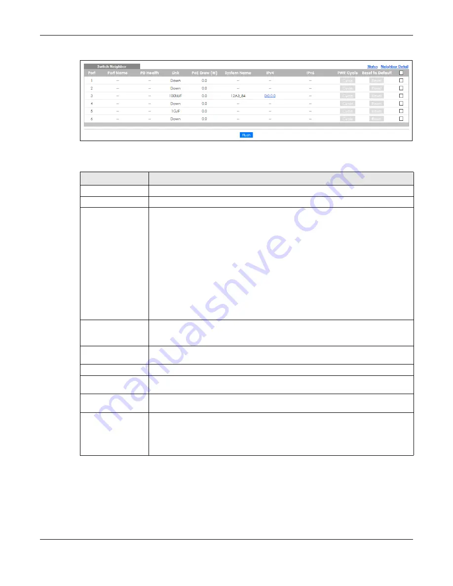
Figure 66
Status > Neighbor
The following table describes the fields in the above screen.
Table 22 Status > Neighbor
LABEL
DESCRIPTION
Port
This shows the port of the Switch, on which the neighboring device is discovered.
Port Name
This shows the port description of the Switch.
PD Health
This shows the status of auto PD recovery on this port. See
more information on how to enable auto PD recovery on the Switch and ports.
• Red: The Switch failed to get information from the PD connected to the port using LLDP,
or the connected PD did not respond to the Switch’s ping requests.
• Yellow: The Switch is restarting the connected PD by turning the power off and turning it
on again.
• Green: The Switch successfully discovered the connected PD using LLDP or ping.
•
–
: Auto PD Recovery is not enabled on the Switch and the port, or the Switch does not
supply power to the connected PD.
Note: The status will NOT be updated instantaneously after enabling or disabling
the
Active
switch in the
Advanced Application
>
Auto PD Recovery
screen
(see
for details). It will wait until the configured
Resume Polling Interval (sec)
has lapsed.
Link
This shows the speed (either
10M
for 10Mbps,
100M
for 100Mbps, or
1G
for 1 Gbps) and the
duplex (
F
for full duplex or
H
for half). This field displays
Down
if the port is not connected to
any device.
PoE Draw (W)
This shows the consumption that the neighboring device connected to this port draws from
the Switch. This allows you to plan and use within the power budget of the Switch.
System Name
This shows the system name of the neighbor device.
IPv4
This shows the IPv4 address of the neighbor device. The IPv4 address is a
hyper link
that you
can click to log into and manage the neighbor device through its Web Configurator.
IPv6
This shows the IPv6 address of the neighbor device. The IPv6 address is a
hyper link
that you
can click to log into and manage the neighbor device through its Web Configurator.
PWR Cycle
Click the
Cycle
button to turn OFF the power of the neighbor device and turn it back ON
again. A count down button (from 5 to 0) starts.
Note: The Switch must support power sourcing (PSE) or the network device is a
powered device (PD).
Содержание GS1350 Series
Страница 19: ...19 PART I User s Guide ...
Страница 42: ...42 PART II Technical Reference ...
Страница 291: ...GS1350 Series User s Guide 291 Figure 218 Example Lock Denoting a Secure Connection EXAMPLE ...
Страница 381: ...381 PART III Troubleshooting and Appendices ...


