Chapter 38 Cluster Management
GS1350 Series User’s Guide
301
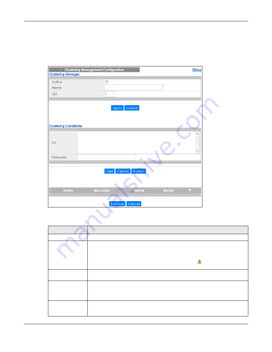
38.3 Clustering Management Configuration
Use this screen to configure clustering management. Click
Management
>
Cluster Management
>
Configuration
to display the next screen.
Figure 224
Management > Cluster Management > Configuration
The following table describes the labels in this screen.
Table 150 Management > Cluster Management > Configuration
LABEL
DESCRIPTION
Clustering Manager
The following fields relate to configuring the cluster manager.
Active
Select
Active
to have this Switch become the cluster manager switch. A cluster can only
have one manager. Other (directly connected) switches that are set to be cluster
managers will not be visible in the
Clustering Candidates
list. If a switch that was previously a
cluster member is later set to become a cluster manager, then its
Status
is displayed as
Error
in the
Cluster Management Status
screen and a warning icon (
) appears in the member
summary list below.
Name
Type a name to identify the
Clustering Manager.
You may use up to 32 printable characters
(spaces are allowed).
VID
This is the VLAN ID and is only applicable if the Switch is set to
802.1Q
VLAN. All switches must
be directly connected and in the same VLAN group to belong to the same cluster. Switches
that are not in the same VLAN group are not visible in the
Clustering Candidates
list. This field
is ignored if the
Clustering Manager
is using
Port-based
VLAN.
Apply
Click
Apply
to save your changes to the Switch’s run-time memory. The Switch loses these
changes if it is turned off or loses power, so use the
Save
link on the top navigation panel to
save your changes to the non-volatile memory when you are done configuring.
Содержание GS1350 Series
Страница 19: ...19 PART I User s Guide ...
Страница 42: ...42 PART II Technical Reference ...
Страница 291: ...GS1350 Series User s Guide 291 Figure 218 Example Lock Denoting a Secure Connection EXAMPLE ...
Страница 381: ...381 PART III Troubleshooting and Appendices ...


