© 2016 ZOLL Data Systems, Inc. All rights reserved.
83
CONFIDENTIAL TRADE SECRETS – DO NOT DISCLOSE.
Z
O
L
L
D
o
c
u
m
e
n
t
a
t
i
o
n
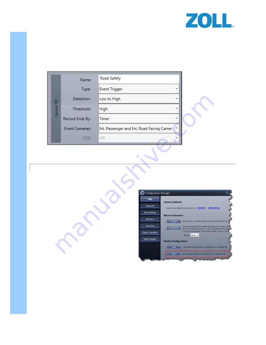
Sensor #2 -
This sensor is linked to the
ORANGE
Digital Ally input wire. The
ORANGE
digital output wire from
Road Safety is to be connected to this input.
To allow the RS-4000 to trigger the recording on the
DVM250/ this sensor MUST always be setup as follows:
1.
Click “Edit” button for Sensor 2.
2.
Configured the drop-down fields as follows:
3.
Click the “Done” button (where the edit button was) and this will save the configurations for this sensor.
DISTRIBUTING THE CONFIGURATIONS
Once the setup of the configurations have been completed the final steps are to save them and then apply them to
the DVM-250/250+ devices.
1.
Return to the
File
tab and under Device
configuration, press the
Save
button.
DO NOT
change the name of the configuration file. The
filename must remain “deviceconfig” (there is
no file extension).
2.
Remove the External SD card from the DVM-
250/250+ camera.
3.
Load the SD card onto your computer.
4.
If any video clips are on the card they must be
moved off of the SD car prior to loading the
“deviceconfig” file to the SD card. It’s suggested
that you create a folder on the computer to
house these files. The SD card must be blank
prior to proceeding to the next step.
5.
Copy the deviceconfig file that you just created from your computer onto the blank SD card.
6.
With the ignition off and no events recording
, insert the SD card back into the camera.
7.
Turn on the vehicle’s ignition and allow the camera to completely start up. Once the camera has
completely finished its ignition start-up sequence, the configuration will be loaded into the cameras
memory.
DO NOT remove the deviceconfig file from the SD card.
The camera should now be setup to receive triggers from the RS-4000 device.


